|
Build Blog Overall Blog Last updated 06-22-2023 **** May take some time to load due to many pictures- Please wait***** |
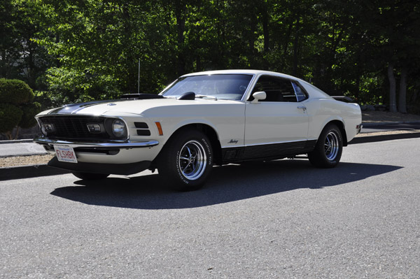
Page 1
Note that since tis initial build things have changed. The car has evolved into more of a drag car and the current HP is 670
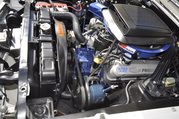
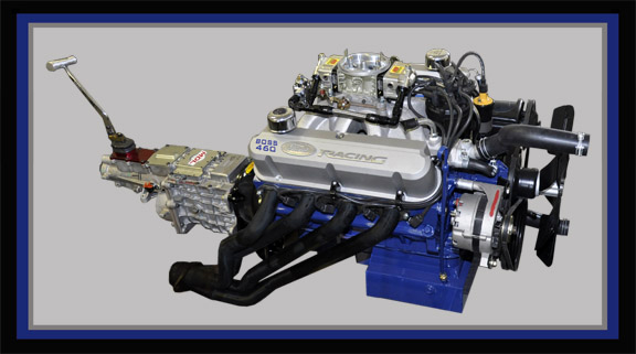
Engine: Ford Racing Boss 351 Block, that is 460 ci, with Z heads
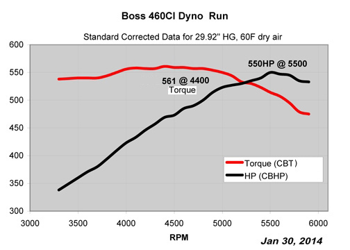
550HP and 561lb.ft on pump gas with a very streetable engine.
13" Hg vac, so my power brakes will work
Ford Racing Boss 351 Block, that is 460 ci, with Z heads (Excellent support
from Ford Racing)
Victor Jr Intake, port matched/polished. Carb surface angle milled 0.3"
front to 0" back to help shaker fit under the stock hood.
AED 950HOM carb, 1/4" phenolic spacer (Excellent Customer AED support)
MSD 85840 STEEL GEAR Distributor (clearanced/modified to work with intake, and
black cover to look more stock)
MSD Digital 6AL box, Blaster 2 coil (Painted to look more stock with yellow
top/black can)
Victor Mechanical Fuel pump (sand blasted to look more stock and not chrome)
Holley pressure regulator with custom fabbed bracket behind carb allowing pump
to carb fuel line to be routed on drivers side of car for stock appearance.
Taylor Pro Spiral 8mm wires
All AN-8 fittings/hose and 1/2" SS lines from tank to carb. Aeromotive
Prefilter with shutoff before pump, and another before carb.
FPA full length headers 1 3/4" pipes entire length with 3" collectors-
Some minor tweaks were required near steering box and idler arm. Black ceramic
coated after test fits.
Fuel pressure gauge sensor on adjustable regulator,with gauge mounted inside
car
Vacuum, Oil Temp, Oil Pressure, Water temperature, Voltage, Wideband 02 mounted
inside car
Driveline Continued:
Quicktime scattershield w/157 tooth flywheel
Hydraulic Clutch setup with external slave from Modern Driveline
Clutch assembly: Heavy duty Kevlar/Kevlar disc rated to 650HP
Roller bearings on clutch pedal for smooth and easy pedal movement
TKO-600 - Modified with carbon fiber synchros, and top surface milled with low
profile cover for more tunnel clearance-Modern Driveline (Excellent support)
Ford racing High Torque Mini Starter
Moser Center Section, 9 in. Ford, Nodular Iron, Detroit Eaton True-Trac, 31-Spline
Axle, 3.70:1, 1350 chrome moly yoke
Strange Alloy Axles with screw in studs, and sealed bearings that do not require
axle seals
Dennys 1350 Nitrous Driveshaft, with chrome moly slip yoke
Leaf spring perches extended and boxed in for added strength
Rear Suspension:
Calvert Split Mono-leafs, car is at stock height
Caltracs- Low profile version given bumpy roads here and advice from Calvert
Racing for better road clearance.
Calvert Racing (Rancho) 9-way Adjustable Shocks
Global West Del-A-Lum Shackles
Front Suspension:- Stock looking
Opentracker Racing Roller Components - Track LCA's, and Drag UCA's with Roller
perches
Roller Idler Arm, all new performance tie rods and adjusters, and other linkage
components
Street and Track Adjustable strut bars
Calvert 90/10 front shocks for race only. Bilstine shocks installed for street
use
Chassis:
Shock towers have been reinforced on the inside and outside. Custom reinforcements
on the inside tying the towers to the frame, and the common 45 degree plate
welded on the outside.
Arning/Shelby 1" drop
Tinman subframe connectors welded in, with additional mounting points bolted
into seat pan weld area with reinforcement plates inside the car.
Custom Driveshaft loop allowing easy removal that bolts into the subframe connector
welded nuts.
Export brace (1 piece)
Control Freak Engine cross brace tying LCA's to the frame.
Other:
Ron Morris adjustable motor mounts- Did not lower the engine, however, used
to to better align the engine side to side and front-to-back.
1/2" Stainless steel fuel line from tank to carb following factory mounting
locations.
AN-8 fittings everywhere in the fuel delivery.
Aeromotive fuel prefilter with shutoff making filter changes easier.
RobbMc 1/2" in-tank sender with AN8 fittings factory installed.
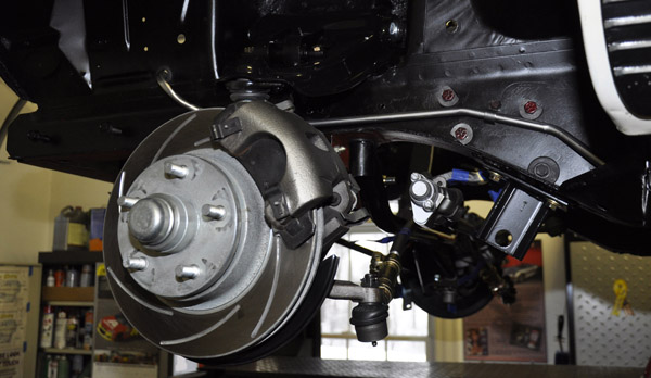
SSB Front Disc brake slotted rotors. Stock style calipers for now.
Rear brakes, drum, with Porterfield R4S Race shoes
Hurst Roll control line lock
Street tires are BFG Radial TA's (yes they will not hook)
M+H Drag DOT Radials 275/60R15 mounted on Drag Lite wheels (28" diameter,
10.9" section width)
Exhaust- Custom 3" pipes from the headers to tips, with MagnaFlow mufflers
and H-pipe. Also the intermediate pipes (headers to mufflers), have ball flanges
on both ends to allow removal and easier transmission access.
Competition Engineering Torque strap- Mounted to back of head and frame
Griffin Exact fit oversized Aluminum Radiator
Aluminum recirculating overflow tank
Reinforced Stainless Steel braided Brake hoses Front/Rear
All Stainless steel brake lines
Jumping Ahead to January 30, 2014
Ran the engine on the dyno and it was 550HP and 561 lb.ft with about 13" Hg of vac. That was all on pump gas with 32 degrees of timing which was optimal. If I went with the Vic Super, could have gotten a bit more at the top end, but then that would not fit under the stock hood with a shaker. The Vic Jr did improve the low end torque over the Ford spec. Dyno work/tuning was done at PK Machine, Fitchburg, MA, by the owner Paul- Did a great job!!!
Dyno Run Video
Now going back to what lead up to the Dyno Run.
December 2013
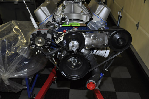
Engine pics
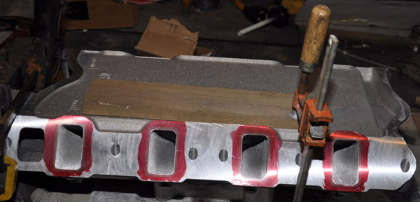
Some of the initial intake work.
Heads already port matched.
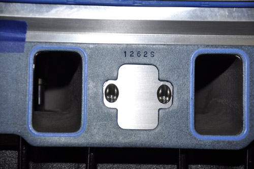
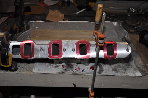
Port matching and polishing the Victor Jr. Intake. Runners were cleaned up, especially along the short side.
Some things did not like up exactly, such as the 1970 351W power steering bracket, so it has to be lengthened slightly to work with the water pump (more on that below). One of the challenges is with the alignment of the pulleys. This was an initial mockup.
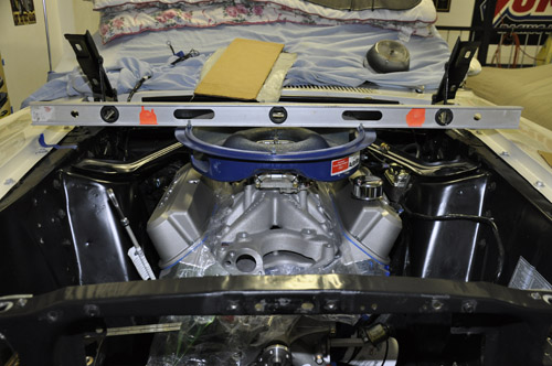
January 2, 2014
Initial engine fitment. The engine was installed many times to mock u various elements during the build.
Wanted to get a general idea how everything lined up with the top of the fenders.
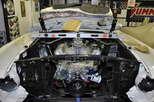
Yes that is a fiberglass unit that I plan on butchering up top make fit.
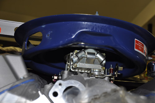
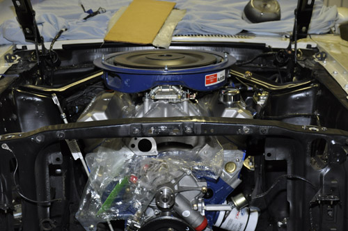
Oil pan clearance is minimal. Inside of the oil pan there is less than 1/2" of clearance below the windage tray, so no room for clearancing, and with the stroke, no room to move the tray up.
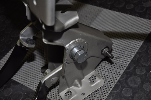
January 12, 2014- Clutch Assembly
The Car was previously an Automatic and is being changed to a 5-speed. The Brake/Clutch assembly was restored with roller bearings to make pedal travel smooth.
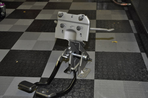
The large support washers were welded in place to make things more secure.
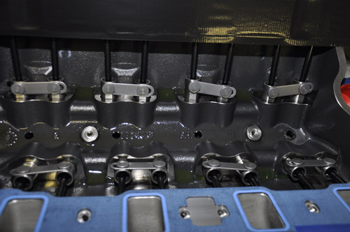
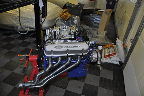
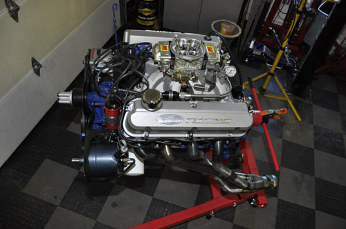
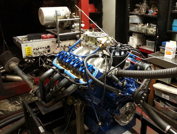
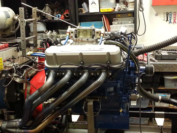
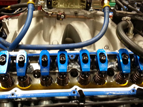
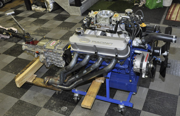
January 13, 2014
Completed engine assembly getting ready for the Dyno
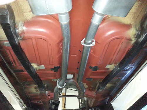
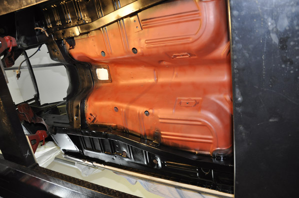
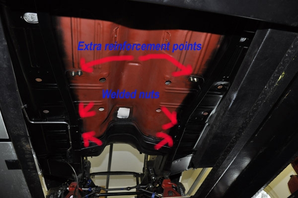
January 19, 2014-Chassis Reinforcement
Tinman subframe connectors with an added bracket under the seat pans. At this point the car was still on its OEM suspension and wanted to weld in the connectors before removing the front/rear suspension to minimize anything being twisted. Now that the rear is pulled out, I can drop this exhaust that was all one piece. Chassis reinforcements that included, Timman subframe connectors, and inner and outer shock tower supports. There are also 2 nuts on each inner side of the subframe connectors that are welded in, so later I can bolt the driveshaft loop in, and make it easy to remove. The driveshaft loop also has a heavy rectangular steel cross brace that will add some stiffening.
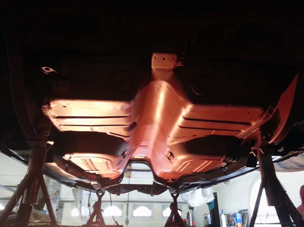
There is a bracket under the carpet just on the edge of the seat pan that 2 bolts on each side will go through and into the tabs welded onto the connectors. I felt it was better to do this, versus welt to the floor pan for strength.
Once welded, all suspension and everything underneath was removed and the cleaning up and painting continued.
January 30, 2014: At the Dyno shop
See the dyno graph and video at the top of this page.
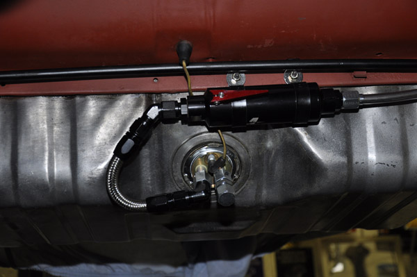
February 14, 2014- Fuel System
To feed the 950CFM on top of the engine I went with 1/2" line from the tank to the carb.
I had InLine tube bend me the 1/2" tubing front and rear section so it was about 75% there. I bent my own pump to carb piece from a straight length. When I placed the order I asked them NOT to flare any ends so I could flare them myself for AN8 fittings and install a pre-filter near the tank.
Now with the bigger tubing, I had to do some additional bending and re-bending in areas which I used a good quality bender. Since the tubing was already bent, there were areas, near the say bar that I had to make my own jig out of pipe to make some additional bends since the bender would not fit. This was needed to move the line slightly to minimize any interference. Even with the pre-bent tubing to start with it took a full day to get everything done. The line has a nice tight fit, and is tucked right up in the rear wheel well. It is a PIA to bend this stuff.
AN-8 fittings everywhere.
I used an in line prefilter from Aeromotive with shutoff making filter changes
easier without taking a gas bath.
RobbMc 1/2" in tank sender with AN8 fittings factory installed. The sender
has a return port that I am currently not using, but its there if needed. To
support the fuel filter I took 2 strips if stainless steel flat stock and made
a bracket to secure it to the underside. The brackets were bead blasted then
painted to match the filter. On the inside edge of that flange where the gas
tank sits, I welded in 2 studs, so I can easily unbolt the filter for cleaning.
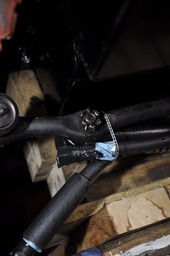
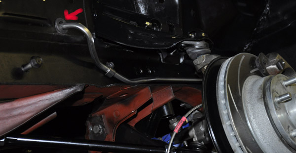
The one place that I could not use AN8 fittings was near the front torque box
where the front and rear line sections connected. The front line could not be
flared before installing, otherwise the nut would not slide through the torque
box, and it could not be done after since there was not enough room to get the
flare tool up there. So I used beaded stem flares (bubble flare like on an OEM
line) there and slipped over rubber hose and clamps like the OEM install. If
you are replacing the torque box, then that is an ideal time to provide more
clearance to slip the flared line and nut through.
Sway bar area was a pain and I has to be sure that with the full motion of the bar it would not contact the line. I had to make the line go back slightly and also had to relocate the mounting bracket, and along the tank, it has to be lowered slightly. There is a clamp at the corner of the tank area to secure the line. All of the brackets I used were Stainless.
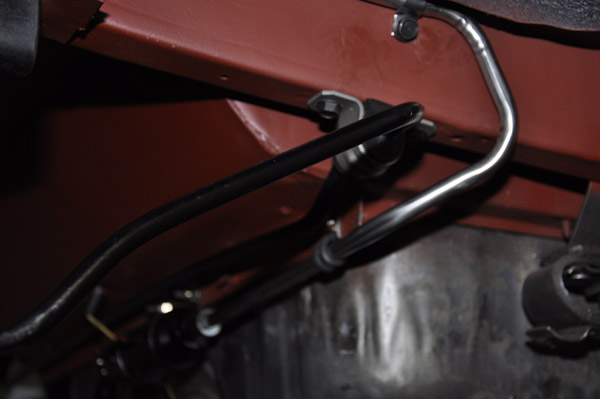
I also had to do some tweaking on the front piece to get everything to fit properly. Where it goes through the fender skirt, I had to make that hole larger with a step drill in order to fit the AN-8 nut through. Just in case I ever need to pull the line out I did not want to flare it after sticking it through the hole. I just picked up a larger grommet at Lowes that fit perfectly.
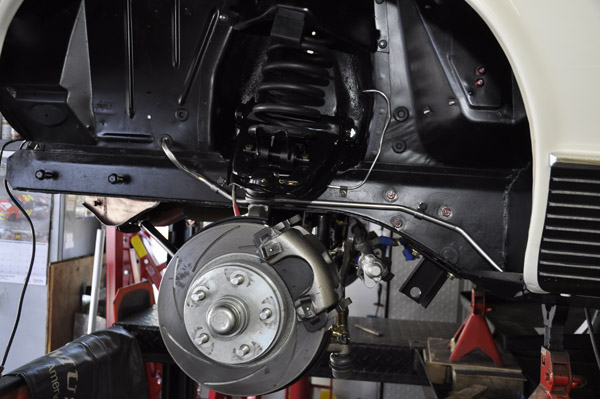
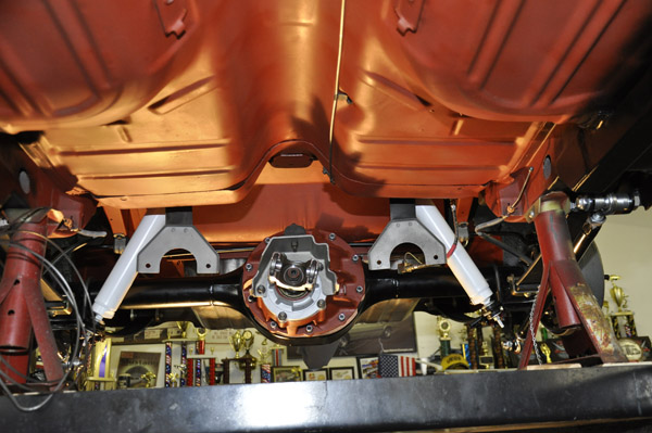
Here are some pictures of the front suspension install.
Front Suspension: Goal is to be somewhat stock looking
Opentracker Roller stuff: Track LCA's (reinforced), and Drag UCA's with Roller
perches
Roller Idler Arm, all new tie rods and adjusters. Restored the center link.
Street and Track Adjustable strut bars
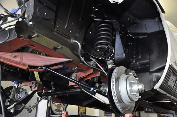
Control Freak cross brace that ties the LCA mounting points to the frame.
Calvert 90/10 shocks for race only. Koni shocks for street use.
While I was at it, I replaced the rest of the steering components as well
The Control Freak brace is nice piece but did require some modifications to
line up properly.
The 2 spacers that make contact with the LCA mounts needed to be clearanced
about 1/8" (ground down) so everything would be perpendicular, and the
section that mounts to the underside of the frame needed a 1/8" washer
(see arrow) to move it down slightly so the slot in the bracket would line up
with the LCA adjustment bolts. Took about 1 hr to make the mods since I ground
down just small amounts at a time until everything lined it.
The other nice thing about it is it is about 1/2" lower that the OEM one and does not have that curve that follows the oil pan, so extra clearance.
At this point I still need to finish the brake lines, but you can see the SS braided hoses.
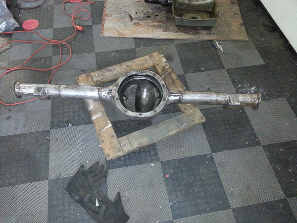
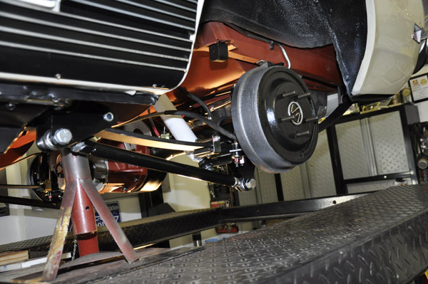
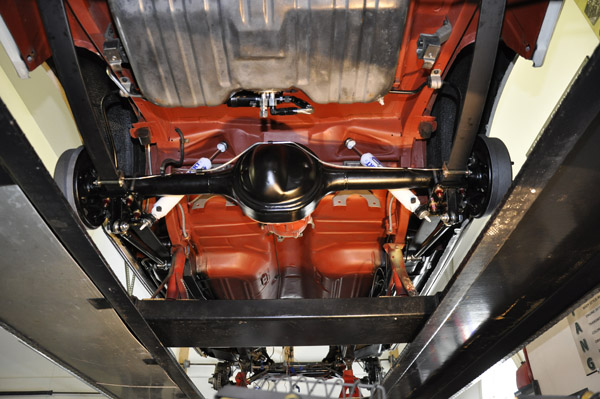
February 16, 2014- Rear End
When boxing in the spring perches, I figured that I would do all of the welding with the rear assembled (old diff and axles installed) and that would help to minimize any warping from welding. I also made a jig out of 3/8" thick 3" angle iron and clamped that on the rear to support it as well. To box in the spring perches, I used 2" U-channel. The U-Channel steel made it easy to box them in. The welding was also done in a stitch fashion to keep from overheating the tubes.
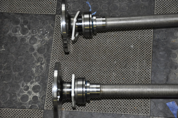
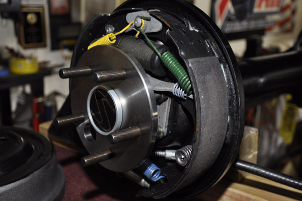
After talking with Strange Engineering about my application, they made a set of custom 31 spline axles, and it took about 2 weeks to get them. The axle bearings have the integral o-ring seal so the seal normally in the axle tube is not used. The axle flanges are also much thicker than the OEM plate, and the wheel studs are the screw in version.
The one thing I found out using these bearings is that the hole in the brake backing plates is almost exactly the same size as the bearing, so the 0-ring would not slide through. I clearanced the backing plate hole just slightly larger then the O-ring so it would pass through without getting nicked.
I also talked with Moser Engineering on the Center Section. Went with their Nodular Iron, Detroit True-Trac, 31-Spline section with 3.70:1 gears and a 1350 yoke. Since I am going with the TKO-600, and the first gear is 2.87, along with the engine power profile, this ratio made the most sense.
February 21, 2014- Rear Braking
Used stainless break lines, and braided flex line. I am waiting on the brake shoes (Porterfield R4S high performance street/autocross shoes) and then I can complete the rear. The Global West Del-A-Lum shackles have been on back order, so hopefully have them in a week so I can get the rear installed.
Porterfield R4S shoes
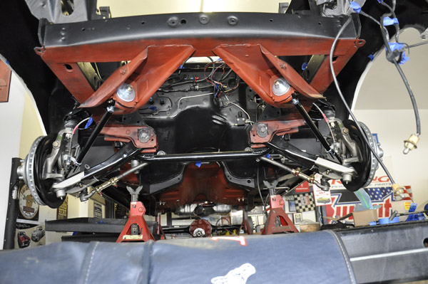
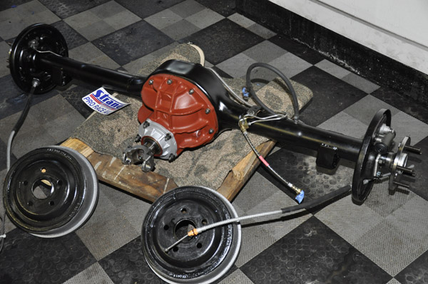
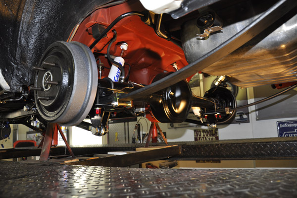
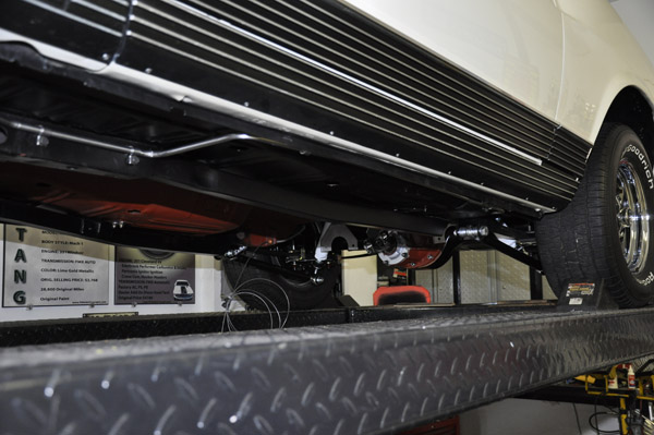
March 2, 2014
Its a roller now complete with working brakes.
Installed the rear, along with the caltracs, Calvert split mono-leafs at stock height, Calvert/Rancho adjustable shocks, and Global West Del-A-Lum shackles
Initiallially installed the CR44130 (for 67-70 mustang), however, after talking with Calvert,went with the CR44116 (for 64-66 mustang) since they are a shorter and will provide more down movement. The Caltracs on a drag strip will prevent squatting, thus shock compression, however, on the street hitting a bump, there is not enou shock compression travel without bottoming out.
Hydraulic Clutch master installed along with the Hurst Roll Control/Line lock. Given the tight space, what a PIA it was to work with the stainless brake lines.
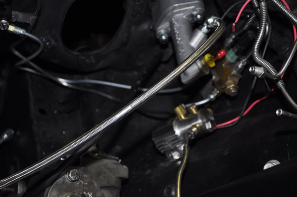
And the brake system is complete, and functional with no leaks. Wanted to get the brake system complete to be sure before I installed the steering column or anything else so I can work in there. For the SS brake line, I purchases the pre-bent lines and modified them as needed. What can just barely be seen is the proportional valve mounted on the rear firewall to the left of the steering column hole.

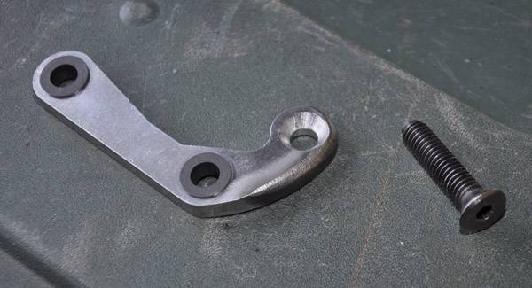
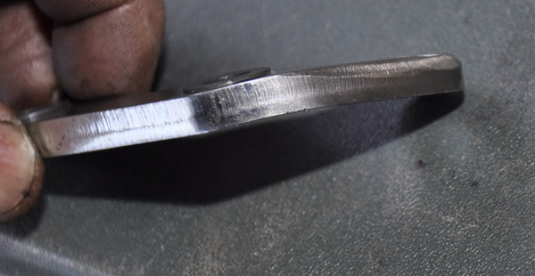
When installing the bracket inside of the car that the clutch master bolts to, the clutch pedal lever arm was very close to the fuse box, so the arm had to be slightly modified to provide clearance not to hit the box. Had to replace the hex head mounting bolt to the clutch pedal with a countersink head mounting bolt, and put a slight bend to the top of the lever. Everything is still in line and moves easily with the heim joint rod ends. Note that on one side is the fuse box, and on the other side outside the firewall is the power brake booster so not much wiggle room to fit this in the space.
March 10, 2014-Engine and Transmission Work
I am continuing to make progress. This weekend dialed in the scattershield and I was fortunate that the Quicktime was within .004" (.008" total runout)so no offset dowels were needed.
Then did one last assembly to make sure everything fit together and was lined up before dropping the engine in.
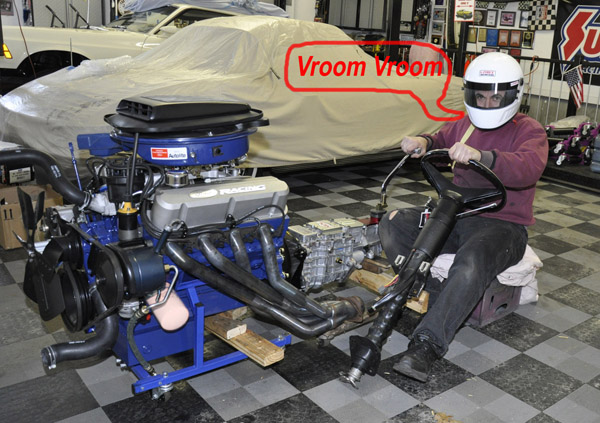
But before the engine went in, I needed to get a feel for it
Shaker still needs to be modified to fit under the hood. Fingers crossed that
it will work.
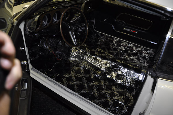
There are so many things to do while I am waiting for parts or help, I can always find something to do. While I was waiting for my wife to help with dropping the engine in, finished getting the gauge cluster, steering column in, as well as the dynomat.
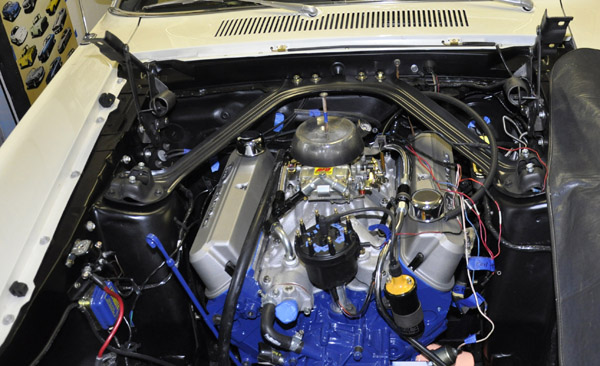
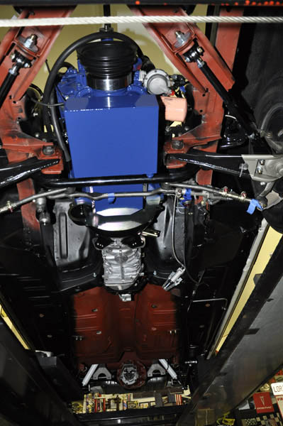
March 11, 2014-Engine Install
It was just going to be my wife and I installing the engine so I decided to install the engine and tranny separately. The engine went in pretty easily, since again there was lots of practice mockups previously. Once I get the MSD box installed, and some of the other wiring, I will wrap the remaining wires that are hanging around for a clean stock look.
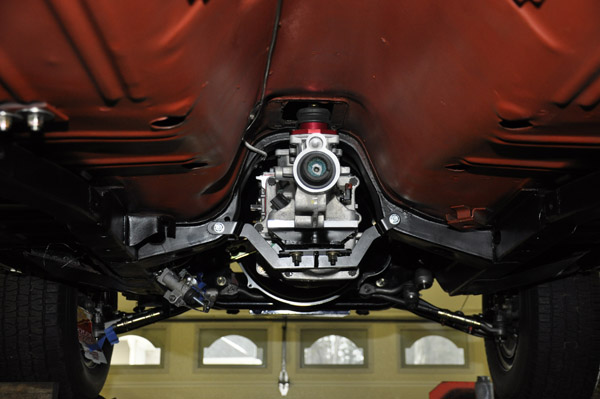
March 12, 2014-Transmission Install
I had Modern Driveline modify the top of the transmission and install the low profile covers to provide added clearance. As a result, the only mods I made with in the transmission tunnel was to dimple the tunnel above the transmission vent, and 2 dimples in the floor support for the 2 pan head bolts that mount cover in front of the shifter. Right now the engine angle and the trans tail shaft location from the top of the tunnel are at the same location/angle as the engine/trans I removed. I still have about another 3/8" I can move the transmission up. Note that the transmission is already up 1/2" more than where the cross mount normally sits. Once I get the car to the ride height, I will check the driveline angle again.
Currently waiting on getting my headers back from being ceramic coated and then I can button up the rest of the steering linkage and clutch linkage. After sliding the headers up and down at least 20 times to make clearance modifications, I have a process where I can slide them up from underneath without scratching everything. Just can not have the power steering cylinder installed and need the idler arm dropped.