|
Build Blog This page Last updated 7-8-2014 **** May take some time to load due to many pictures- Please wait***** |
Page 2
March 17, 2014
Made some progress over the past week.
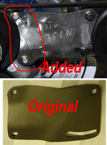
Early on when the engine was on the stand getting all of the accessory brackets to line up with the Ford racing water pump required a few modifications. The bolt locations were different from a 1970 351W. The rectangular PS Pump bracket, had to be extended to line up properly with the water pump bolts. This required welding an approximate 1" piece to the end to extend to the left, as well as shift the lower bolt down, and re-drill holes. Also behind the PS bracket and Alternator bracket a small spacer was required on one bolt for each bracket for alignment out from the pump. The spacer material was made out of SS round stock and sized to match the water pump locations so they look like they belong.
Brackets have since has been cleaned up and powder coated.
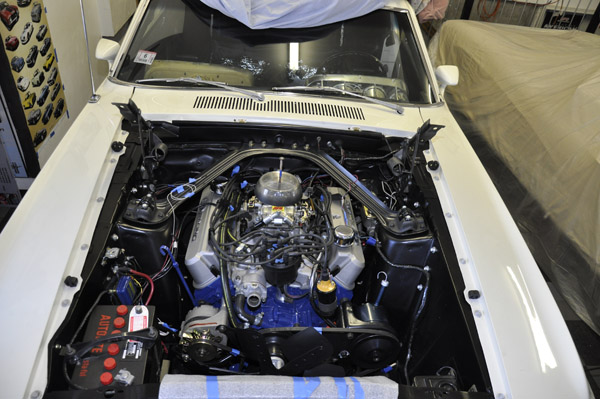
Pictures during initial mock-up:
Still waiting on my headers from being ceramic coated and my Griffin radiator so I can't button everything up on the engine and trans yet, so plug wires are just sitting there.
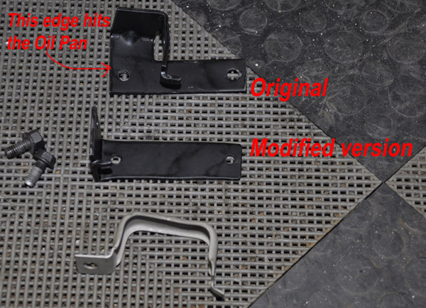
The bracket that holds the PS hoses requires an offset since the wider oil pan interferes with the original bracket, so an offset version needed to be fabricated. The new bracket could not have that reinforced gusset as in the original, so I used thicker stock to compensate and tapped the bolt hole.
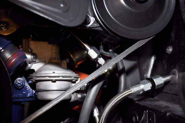
The area where the power steering pump is was very congested with the 1/2" fuel line, and and power steering hoses. I took a stock power steering High pressure hose and had to modify the bends to clear the shock tower, and the fuel pump lines. With the raised port heads being a little taller, the accessory mount hole pushes the pump a little closer to the shock tower, causing a clearance issue with the hose at the back of the pump.
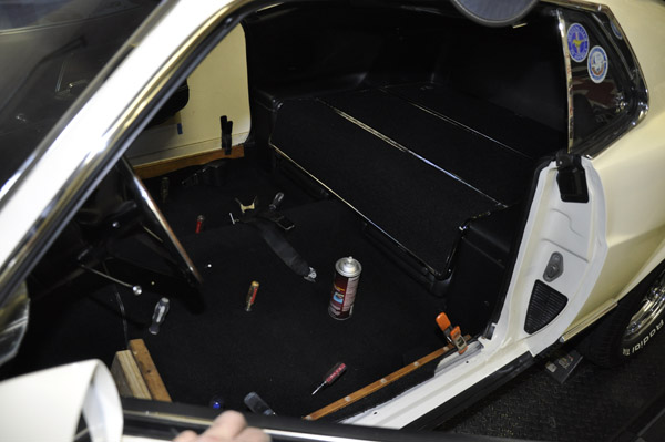
While waiting on other parts, I jumped back to the interior getting the carpeting and rear seating area installed. I always like to use a little spray adhesive along the outer areas to hold the carpeting tight. That is where the wood and clamps are mounted.
March 27, 2014- Its alive!!
Today I got the engine to the point where it can be started and it was the first time the engine ran in its new home. Took a bit to keep it going the first time since it is very cold here (30 deg F), and no choke on the carb.
Here is a short vid of the engine running with open headers. Sounds great and
shook the house. Such a sin to install mufflers
Expecting my drive shaft from Dennys Driveshaft in a week, and then it can move under its own power. Still much much more to go before it is road ready.
Hoping to have the rest of my Autometer Sport Comp 2 gauges this week. Plan is Oil pressure and engine temp in console ashtray pod. Inside of the console box will be, Vacuum, Oil Temperature, Fuel pressure, and Volts. The gauges have low/high level sets that can trigger other functions.
April 6, 2014-Driveline completed
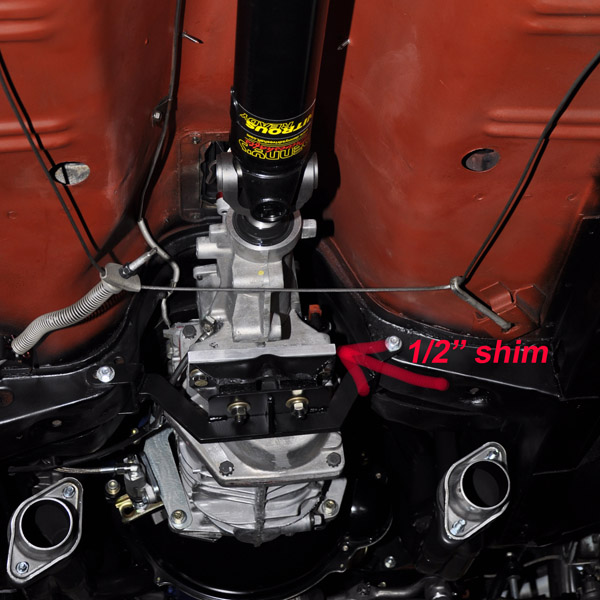
The past few weeks have been productive with closing in on completing the 70. Got my driveshaft from Dennys Driveshaft this past week, so was able to finalize the driveline angle and it is close but still needs some tweaking. Once I get all of the interior in, as well as when the suspension settles I will check everything again and do any final tweaks .So far all I did was to shim the transmission up into the tunnel 1/2" above the x-brace. I used the Modern Driveline Trans cross member and also the Ron Morris mounts, but kept the engine at stock height. If needed, I still have another 3/8" I could tuck the trans up in the tunnel, and may have to shim the rear a 1 degree to get them parallel. Still TBD.
The driveshaft from Dennys is one of their Nitrous ready ones, with a chrome molly trans yoke, and front/rear 1350 solid u-joints.
With the driveshaft installed, and with the rear on jack stands, I was able to check out the transmission and shift through the gears. This also allowed me to break-in the center section. Even though there is no specific procedure for break in, Moser recommended running the Detroit Eaton Tru Trac on jack stands so there is no load for a few miles to heat it up, then light driving after for a bit, with a 500 mile break in, also same for the TKO600 break-in. Going to need to resist any burnouts for a bit. So far everything is working properly.
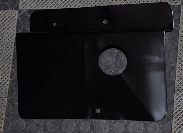
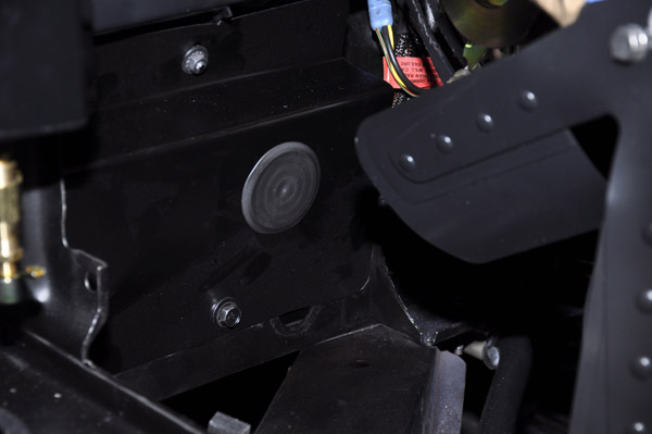
Also been buttoning up the engine bay. The MSD Digital 6AL2 box is installed under the battery, so I fabbed a shield to hide it, as well as some relay modules for switched power that goes into the cabin for the accessories and gauges. To make adjustment of the rev limiter and see the MSD indicator light, I have a removable body plug. The shield also has some x-ribbing to stiffen it a bit.
April 6, 2014-Gauges
When I needed a change of pace I worked on the console and finished it this weekend. I kept all of the stock dash gauges, but wanted to add the following:
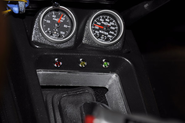
Front of Console: Oil Pressure, Water Temp
Inside Console box: Vac, Oil temp, Volts, Fuel Pressure
These were Auto Meter Sport Comp 2 with programmable warning indicators.
Console pieces made out of 1/4" Sintra
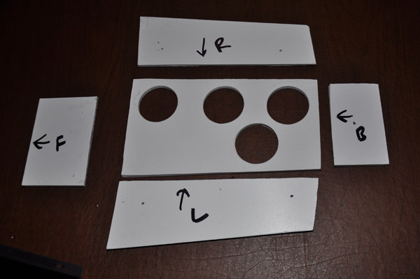
Surface was painted with chipguard then oversprayed with the charcoal metallic
paint to match the rest of the interior. The chipguard provides a texture close
to the rest of the interior plastic.
The switch to the left is the line lock enable to prevent accidental engagement
of the line lock (momentary) button on the shift handle. There is also an external
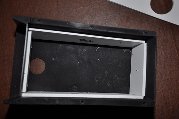
console indicator showing when it is enabled. The Gauge assembly slides into
the box and is secured with Velcro. For easy removal, you can just pull the
loop to the right and have access to the backside without removing the console.
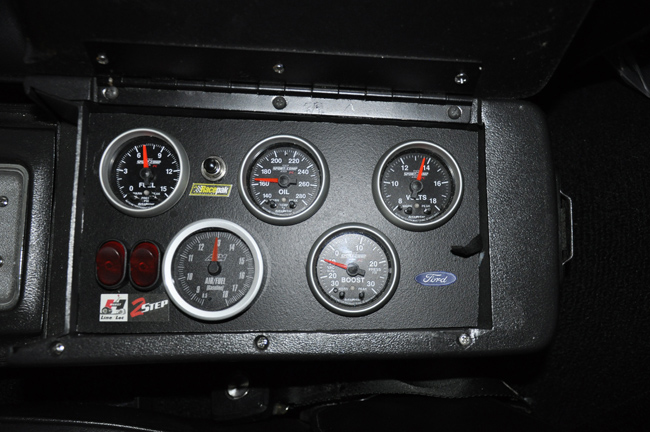
The 3 LED's are as follows:
RED- If any of the gauges are not within the normal operating range, it lights.
Important since the box cover will be closed most of the time.
Green- Indicated that the Line Lock is enabled with the box switch.
Amber- Line Loc is engaged
Lastly, since I wanted the dash gauges to work, along with these, I tapped the oil pressure log to add the Autometer sender.
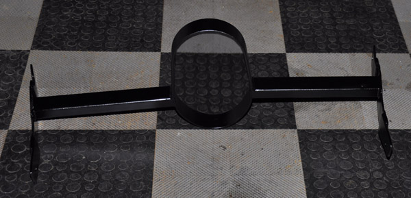
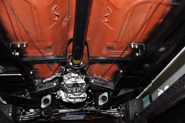
April 14, 2014- Driveshaft Loop
Among many parts of the stang I worked on this weekend, one was the driveshaft loop. When I picked up the Tinman Subframe connectors, I also picked up one of their weld in drive shaft loops. After test fitting it, I really did not like the fit. If it was tucked completely up against the floor (which is best), then there was not sufficient clearance on the lower side of the driveshaft. It was meant to be centered in the subframe connectors, however, that keeps the cross bars down about 1" from the floor taking up space for the exhaust, as well as will force the parking brake cable to rub along it.
My Goals:
1. Have the cross braces tucked completely against the floor
2. Make it bolt in, so I can be easily removed
I was also inspired after looking at Buckeyedeamons custom DS loop and how great that fit
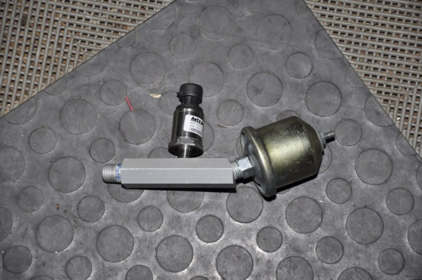
This is what I started with (pic form Tinman web site)
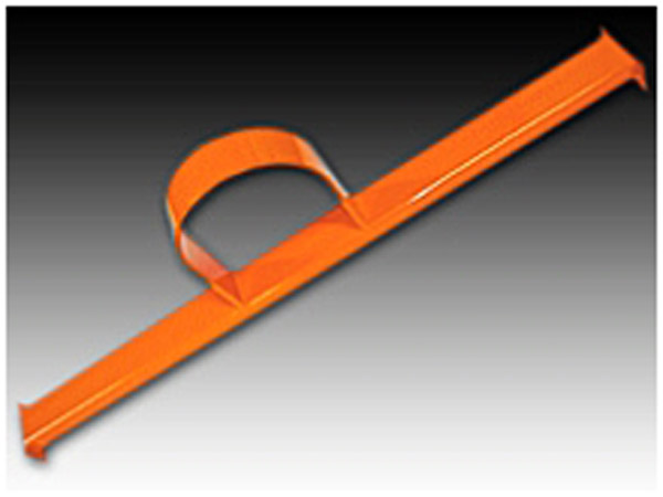
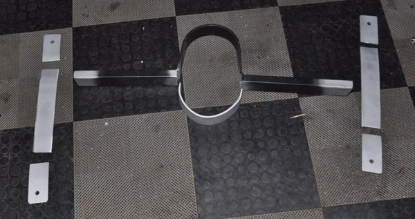
I chopped out the straight part of the loop on the lower side and formed an additional loop out of 5/16" steel bar using the top portion of the loop as a fixture and bent the steel using clamps. Also by removing that center piece, I could slightly change the cross bar angles so they followed the floor pan.
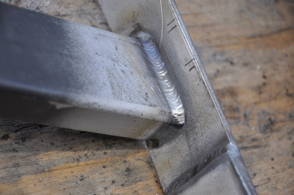
When I installed the subframe connectors, 2 Gade 8 nuts on each side were welded to bolt the loop to. Rather than cut out areas of the connector tubes to make the nuts flush, I opted to weld the nuts to small plates, drill a hole the size of the nut for it to fit into, and then weld that assembly to the connector. Now there are a raised sections at each nut, thus the reason for the ears that you see off to the side. The ears also allowed me to clamp everything in place and really tuck it to the floor for tacking since there are a bends both horizontally as well as vertically in the connectors
My buddies son (Dan B) does an excellent job of welding!
All assembled and painted. What is is not easy to see is that during my mockup, I notched the side braces along the floor pan ribs so they would be right to the floor.
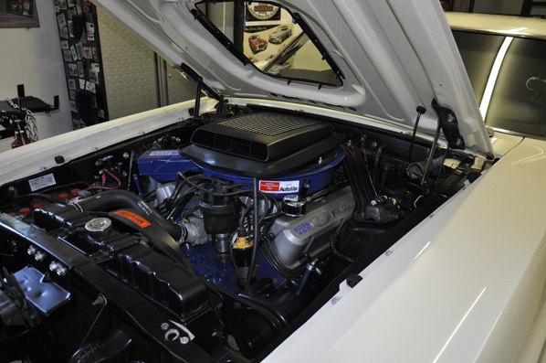
April 17, 2014
The car has been moving under its own power for about a week now and just a few tweaks here and there as well as wrapping up the interior. Should be hitting the exhaust shop in a week, so right now open headers are shaking the house. Yes I am sure I am driving some of my neighbors nuts with it sounding like a drag strip here.
Here is a short vid in the driveway.
Note that I have my shaker installed atop the Vic Jr intake. I will be posting some pics in the next few days showing the mods done to accomplish that.
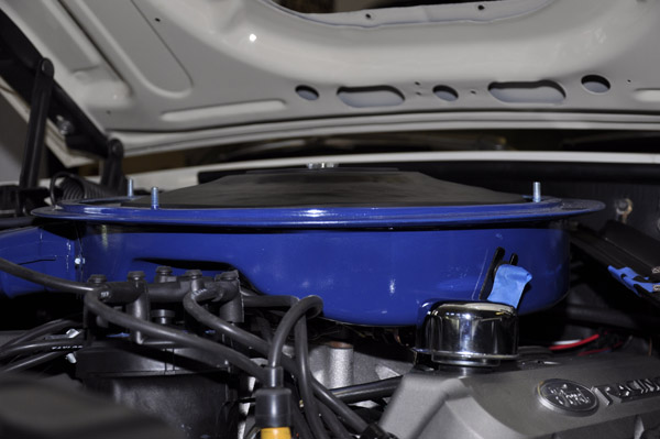
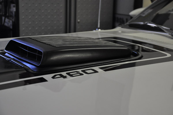
April 24, 2014: Shaker Modification and fabrication
I was determined to get my shaker to fit under the hood with the Vic. Jr intake and still keep it looking somewhat stock.
Few things to note:
1. The carb mounting surface of the Vic Jr was milled .25" at the front
sloped to 0" at the back.
2. I have a 1/4" phenolic spacer
3. Even though I have Ron Morris mounts, the engine is at stock height
Given all of the above, along with the large cap from the MDS distributor and its additional height, this required many modifications to the shaker assembly.
I started off with a FordRamAir fiberglass base. www.fordramair.com
To start, the base needed to sit at least 1.5" lower and also be shifted back approximately .6". The .6" provided the needed clearance for the distributor. Without this rear shift, the modifications to the distributor area would have cut into the flat surface where the filter element sits.
I did a number of mock-ups of the complete solution in order to make this work, however, what you are seeing is a summary and not the various iterations to figure this out..
To lower the base I cut out the center section. In addition to get the base to sit lower I needed to cut out areas around the fuel bowls. The rear fuel bowl was clearanced much less since the complete base was shifted back. This picture shows my initial cuts which were eventually opened up an additional 1".
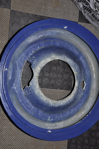
Then the center ring was trimmed down, so I just had the section that rested on the carb. After trimming, this section was about 1/2" tall.
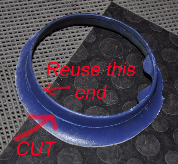
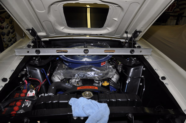
I opted to cast the fiberglass with the assembly installed. To ensure that the base would be horizontal with the hood, I used a long level as a straight edge and measured off of the fender edges. I also placed 2 sheets of heavy plastic over the top of he engine to protect it from the resin, along with 1/4" packing sheet foam in the areas where the fiberglass matting will be added.
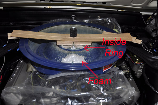
The base was secured in place exactly as it would sit when done. Note that that center ring that was cutout and made smaller is now sitting on the carb. The reason for the foam sheeting was that I do not want the base resting right on the carb bowls, so the foam makes sure that the back side of the fiberglass matting is at least 1/4" away. That also provides extra space so I can add more resin on the backside and smooth everything out.
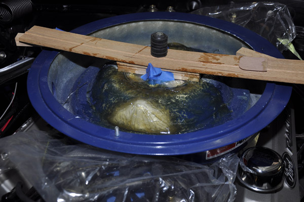
The first layer of fiberglass was applied in the car.
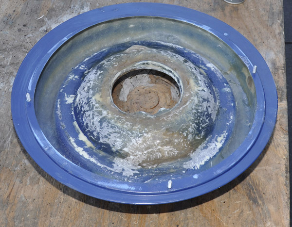
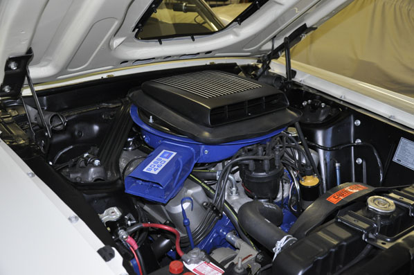
Two additional layers of fiberglass were added after the assembly was removed, and resin was brushed on the backside to smooth everything out. Once cured, it was smoothed out and painted. What is not seen in the pictures was a very minor clearance done above the throttle linkage area.
Dropping the base causes a problem with the lid clearance. I have an AED carb
with no choke. The minimum distance above the carb vent tubes recommended by
AED was .75". I had to take the repro lid and reshape it using a body hammer
and dollies to more of a bowl in order to secure the filter element in place
and also meet the clearance requirement. I ended up with just over 1"..
The next challenge was the midplate. Since I did not lower the engine 1/2", the stock midplate could not be modified enough to work, so I had to fab my own low profile version. It provided the needed hood clearance, as well as worked with the raised air cleaner lid. I also had to make the shaker support bracket mounted to the side since a stock one will no longer work.
April 26, 2014: Torque Strap
Even though I have the Ron Morris engine mounts, I still wanted a torque strap as a backup. The problem was with power steering and everything else up front there was no room.
Since I have a hydraulic clutch and no Zbar, that opened up an area at the back side. Unfortunately I did not notice that open area until most everything was together, including my headers.
I purchased one of the Competition Engineering adjustable torque strap units and liked how it was made. The grade 8 parts alone cost the same so I just got the kit. I only had to modify the frame mounting bracket so it would clear the steering box. Basically created an "L" bracket that could be welded all 4 sides, plus 2 plug welds in the center for added support.. This was welded just behind the steering box and just below the top of the frame rail.
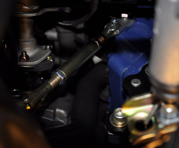
Most likely I will only keep this installed when going to the track, since it does transfer MUCH more vibration to the chassis. With the 2 pins, it can be removed in a minute and just as easily put back.
April 28, 2014: Modified 1970 Mach 1 Exhaust Tips
The car is going into the exhaust shop this week and the installer is 99% sure he can install a full 3" exhaust from the FPA headers right to the back.
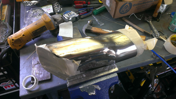
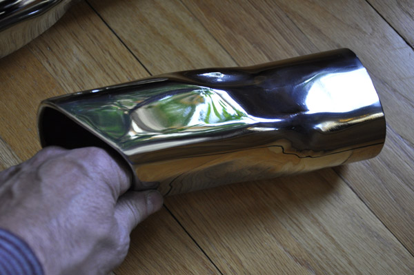
In preparation, I have been working on modifying the original style 1970 Mach 1 exhaust tips with help from one of my friends son (Dan B) who is an expert stainless steel welder and did all of the welding. The idea was to make the tips which are for 2.25" pipes work with 3" getting rid of any restriction.
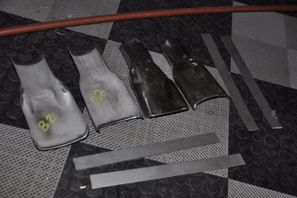
Started off with a set of the "closest correct" repro 70 Mach 1 stainless tips for 2.25" pipe. The end opening was 3 5/8" x 1 3/8" giving an area of about 5 sq in. A 3" pipe has about 7 sq in. If the tips have had another 9/16" in height making them 1 15/16" that would get them to 7 sq in, however, due to the taper in the back, and maintain the original profile it really needs to be about 1" taller. The plan was to slice them in half horizontally and add a 1" section of stainless on each side.
I realize that I could go slightly smaller since the exhaust gas will be cooler as it hits the tips, thus less dense, but since I need to modify them, why not get rid of any restrictions.
1- Pictures of tips cut in half. I pulled a straight line with masking tape down the sides along an area that had no contours, then used a metal cutting blade on a die grinder to get a nice smooth straight line. Also shown are the side pieces of stainless. The tips were 16ga, so the strips are also 16ga 316 stainless.
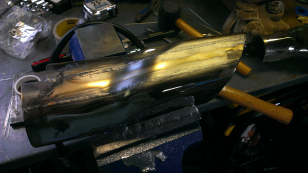
2- Tacking and bending the side strips.
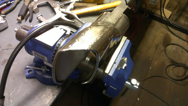
3- During the actual TIG welding, and to improve the quality of the stainless steel welds, the inside of the tip was also purged (shielded) with argon gas. That is why one end is taped closed with a small escape hole, and the other end has Argon being fed in with the blue hose.
4-To get the rolled edge effect, it was too difficult to roll the end of the strip and get everything to line up, so we opted to weld on a 1/4" SS welding rod to the end to give the effect. That was then ground down to blend into the rest of the rolled edging and unless you look inside the tip with a mirror, you cant tell it is not rolled.
5-Initial grinding of the welds to ensure no gaps within the metal or welds.
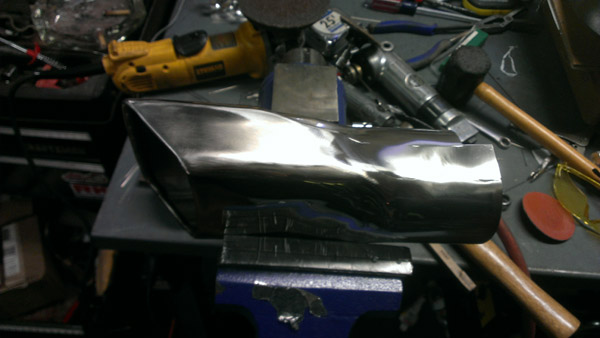
After all the welds were ground down another few hours of final cleaning up. I started off with 120 grit paper on an orbital, then progressed to 220, 320, 400, 500, and finally 600 grit.
After all of the sanding was complete, the next step was three stages of polishing. I used the Eastwood stainless buffing kit on a 10" buffer. Going from the most aggressive buffing combination to the final finish, the steps were: Sisal buff with emery compound, then, Spiral Sewn buff with Stainless compound, and finally Loose Section buff with White Rouge compound. I found that the 10" buff worked very well and the large size minimize the pad from getting caught in the end opening.
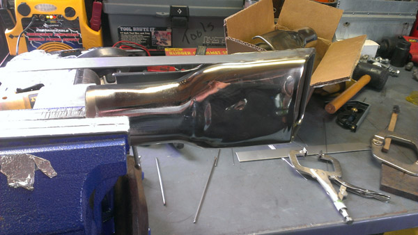
6-Final product all ready to be installed later this week.
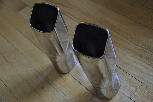
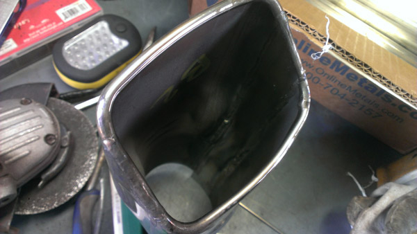
Not shown in the pictures is the backside of the tip, the pipe opening is now somewhat oval. The exhaust person thinks he will need to oval the pipe to clear the gas tank and leaf springs, so this works perfect.
To summarize: The tip opening ended up being 2 1/2 high by 3 5/8" wide (same as original width, only taller), thus 9 sq inches, and the back side opening is oblong, approximately 2 3/4" x 3 1/2" working out to be 7.9 sq inches, both greater than the 3" pipe area, so no restriction and will also slip over the 3" pipe to be welded.