|
Build Blog This page last updated 3-15-2021 **** May take some time to load due to many pictures- Please wait***** |
Page 12
This is the start of a completely new engine rebuild.
July 1-2020- The onset of a new rebuild.
The local track opening was delayed for 2 months due to Covid 19 and as things turned out, 5 days before the track opened I blew a head gasket and flooded the oil and a cylinder with water. After pulling the heads I noticed that there was some wear on a bunch of the valve tips that the head builder suspected it was partially due to very high spring pressures and lots of street miles. This led to needing a valve job and as we all know at times one thing leads to another and here I am doing a complete engine rebuild. The goals for this rebuild are much different than before, and will include titanium valves, new pistons, rods, cam, Dominator carb, adding a vacuum pump, and higher CR to name a few, since the car has evolved into a 99% drag car, and street manners are no longer a requirement.
August 16-2020- Progress on the new rebuild and other work.
At the onset of this rebuild I discussed the goals with the person working on the heads (Duane Busch), and the machine shop doing the short block/Dyno tuner (Paul Krauss at PK Machine). The conservative estimate is to get to 740 HP NA and anything beyond that is gravy. The previous build was 670HP at 6800rpm and 587 lb-ft at 5200, so this will be a significant step up.
Most of the work outlined below has already started with a plan of being all back together by late September 2020 in order to get to the track before the season ends on October 31. With the Covid 19 crap, that has put some delays with getting custom parts.
Summary of the NEW build plans and work to date:
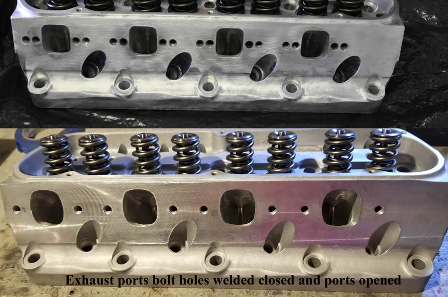
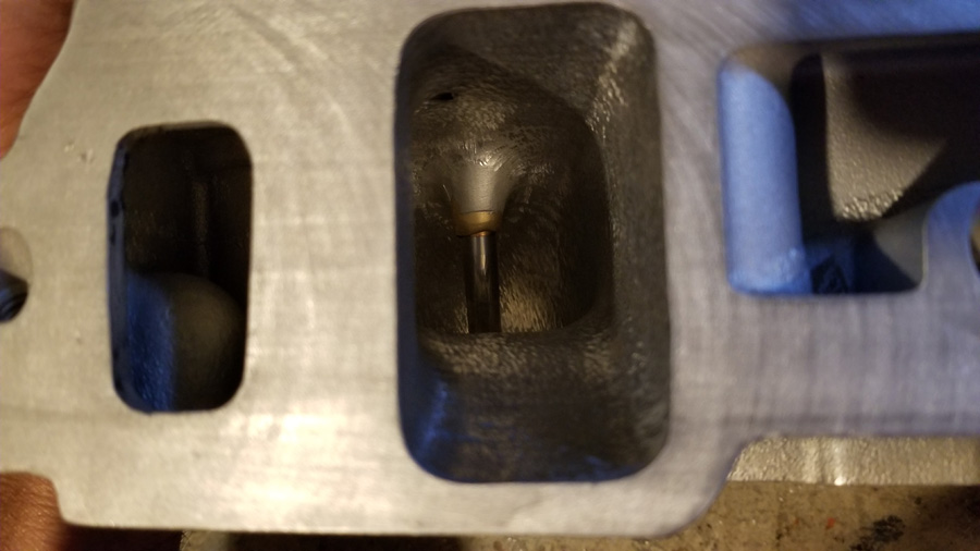
Heads: This new work will take the previous Duane Busch worked Ford Racing Z304 heads and he will now take them next level with even more porting and polishing than before along with opening up the exhaust ports more to take advantage of the 460ci, and a more aggressive cam profile. Previously the valves were increased from 2.02" to 2.10" intake and 1.6" to 1.625" exhaust which were are the largest that would fit. This rebuild is using custom Victory titanium valves (flat faced, hard tip), 1.3" PSI springs (less spring pressure), and PAC locks/titanium retainers. There are two exhaust bolt patterns, so welding closed the inner ones to allow opening up the ports a bit more.
While the heads are being worked, T&D did an inspection and rebuild of the shaft rockers making them like new. They were in very condition and held up well for 4 tough years.
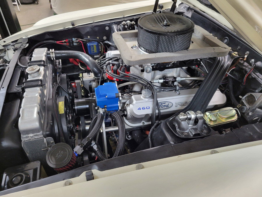
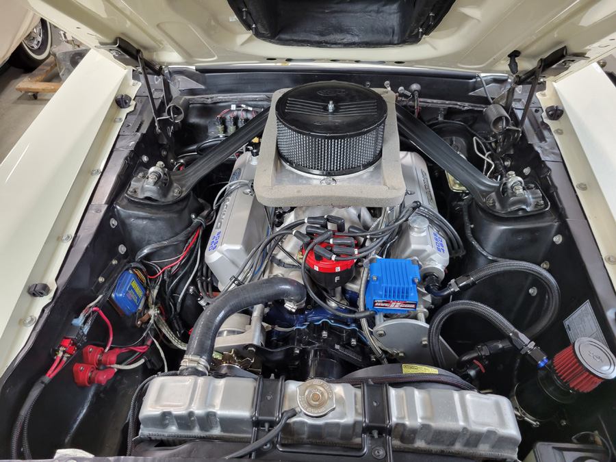
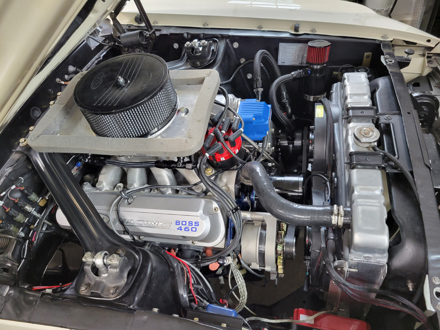
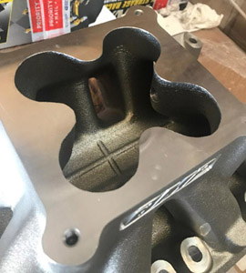
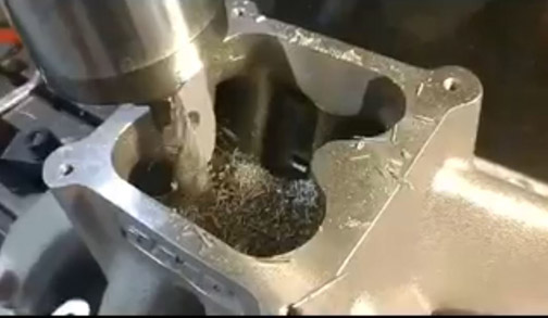
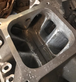
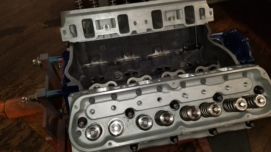
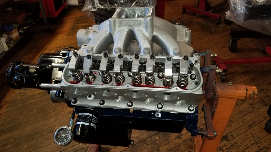
Intake: Going from the 351W Vic Super to a Bill Mitchell SBF Intake with a much bigger plenum area and straighter runs. The intake is being worked by Duane Busch and will include port matching, blending and polishing, along with milling out the cloverleaf to open it up more. Between this new intake and the new Dominator carb my airpan needs to be modified to fit under the hood. I did a bunch of initial measurements comparing the old intake with a 1" spacer and carb, to the new setup and I should be within 3/4" in height. Will know for sure when try and close the hood :)
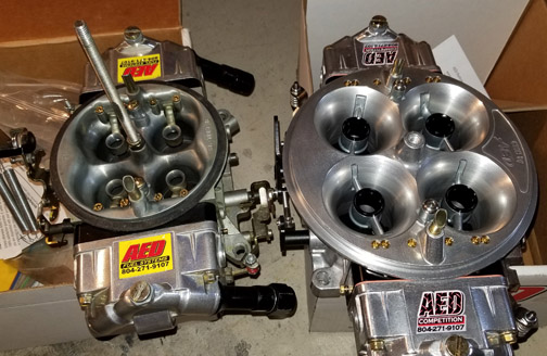
Carburetor: The Bill Mitchell intake will be topped off with a custom built AED Competition 1050 Pro Series Dominator that was set up to run VP Q16 race fuel. This picture compares the new Dominator to the previous 4150 carb that was a 950HO modified. Just a little bit bigger! I stayed with AED since they have treated me very well in the past and their support and responsiveness is #1.
When they built the carburetor it was CNC Ported & machined to my application, including specific sizing, and features. There are fully adjustable billet metering blocks, externally adjustable 4-position linkage, high atomization annular boosters, AED's custom high flow needle & seats & floats. This 1050 has the standard 2.00" bore and a 1.800" venturi and was wet flowed showing 1125 CFM including Q16 fuel.
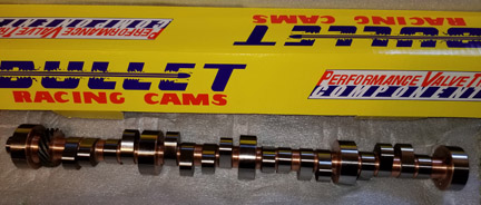
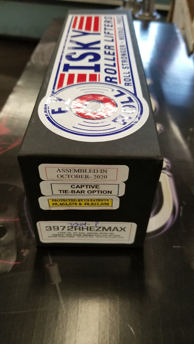
Cam: Bullet Racing Cams did a custom grind to take advantage of the new changes. More details on this later, but increasing the lift and duration to take advantage of the head and intake flow. Bullet was super fast where I had this cam at my door 2 weeks from when I placed the order. Lifters will be the Isky Red-Zone EZ-RollX which have a solid bearing versus needle bearings.
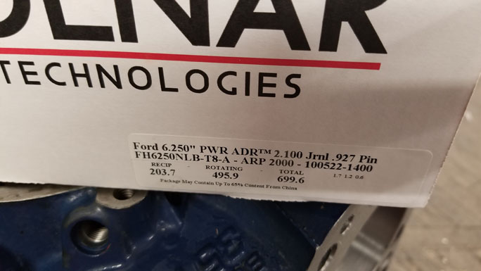
Block: Paul at PK Machine is doing all of the block work. Fortunately the Ford Racing Boss 460 block was in very good condition with the bores in near perfect shape even though I have beat the crap out of it. He is only opening the bore from 4.150" to 4.155". There is room to go more, but rather leave the room in case there are any issues in the future we will have the ability to work this block again. Adding a few additional holes in the valley to allow the oil to drain back easier and improve crank venting.
Pistons: Custom lightweight Diamond Pistons, pins and low tension rings are on order. Also on order is a Star Machine GEN 2 vacuum pump along with all of the goodies.
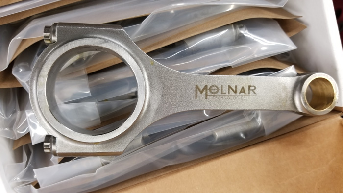
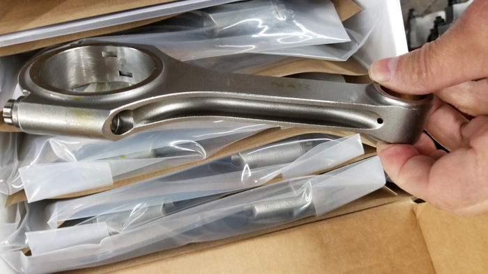
Rods/Crank: Replacing the SCAT connecting rods with new Molnar rods, and reusing the SCAT 4340 forged crank since it looked perfect and passed magnafluxing.
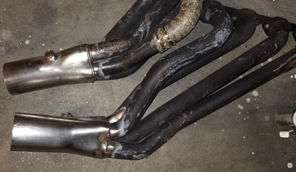
Headers: The collectors were increased from 3" to 3.5". I still need to add a ball flange to bolt to the exhaust when participating in street class events at the track or street driving. After the Dyno tuning and final fitment into the car I will have these ceramic coated. There was one area on the drivers side header that I previously had to oval the tube a little for steering box clearance. Since that reduced the cross sectional area, I cut the tube and spliced and blended in a piece of tubing to maintain the original round cross sectional area as an oval now.
September 1, 2020 - Fan & Water Pump
When I had free time between the above stuff, I finally got to some other things I wanted to do for a while, including replacing the mechanical fan and water pump with electrical units.
For the fan I decided to go with a Ford Contour Dual Fan (Dorman 620-104). It fit my Griffen Exact Fit 24" radiator perfectly. Just needed to fab a few brackets and do all of the wiring. For the fan connectors the Standard Motor Products S827 connectors go right on and the wiring is in Fiberglas sheathing.
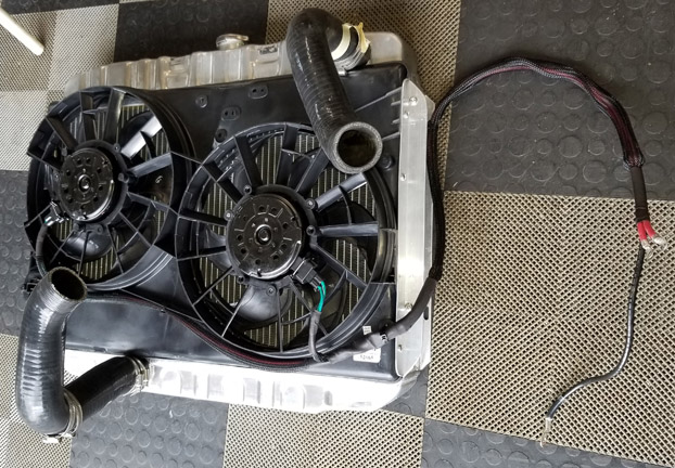
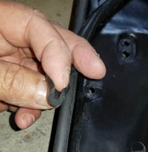
Used a few pieces of angle aluminum to fab 2 end mounting brackets. Inside of the shroud area there are six 2" pieces of flat stock to better support the plastic shroud versus a washer on the inside. Around the edge of the shroud where it rests on the radiator I stuck on some u-channel high temperature foam (McMaster #4869A69) to fill any gaps and provide a cushion to the radiator.
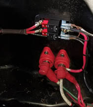
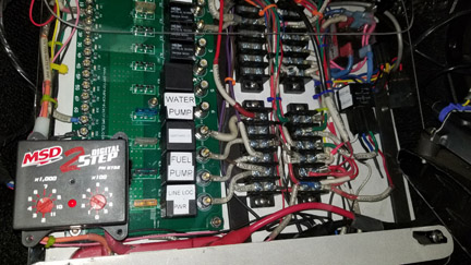
There is a relay panel inside of the car for all of the other electronics, but given the amount of current that these fans use, I added a Leash dual relay block that can handle 70A x 2. This is on the fender skirt close to the main power stud.
I wanted to have some control over the fan and water pump, so where the factory radio that has been gone for years was, I made a switch panel with illuminated switches. When the ignition is off I can still turn on both the fan and the water pump. When the engine is running the water pump "always automatically turns on" using the main relay panel, however, I wanted the ability to shut the fan off at any time. For reference the switch panel above is where the factory AC vents were.
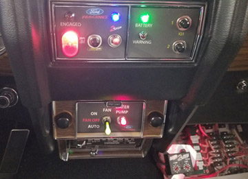
It is hard to see but there is a clear Plexiglas cover over the relay panel and that MSD 2-Step box is attached to the cover so I can easily adjust the launch RPM. The cover also protects the panel just in case the heater core ever should leak.
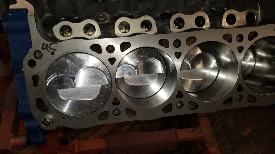
September 17, 2020 - Heads Completed
Heads are done and geometry with the T&D Shaft Rockers looks really good. The head work was done by Duane Busch.
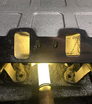
The pic below shows the exhaust ports on the heads with the 2 exhaust port bolt patterns. The inner bolts limited how well the ports could be matched to the headers, so they were welded closed and then the surface refaced. This allowed the ports to be opened more and shaped to better match the header flange.
As expected there was minimal change in the flow since quite a bit of work
was done previously, and the 2.10" and 1.625" valve size did not change..
The updated flow numbers are (done at 28 in Hg on a Superflow 600 flow bench)
Intake Flow
.300 lift 222 cfm
.400 282
.500 312
.600 331
.700 340
.750 343
Exhaust Flow
.300 lift 169 cfm
.400 208
.500. 230
.600. 247
.700. 259
.800. 262
The minimal Cross Sectional area is 2.80", and the port is 245cc. The
ports could be slightly larger, but Duane Busch would prefer to see how they
perform on the dyno before removing any more material. Easier to remove than
to put back :)
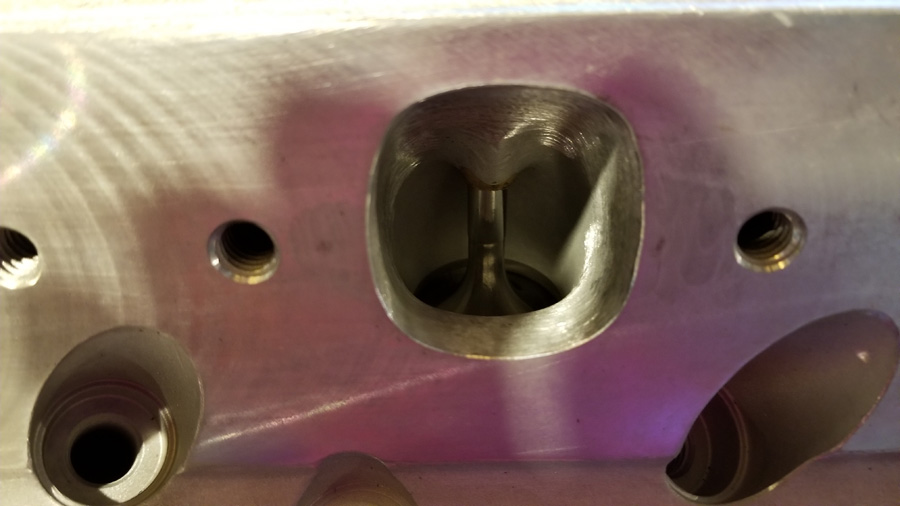
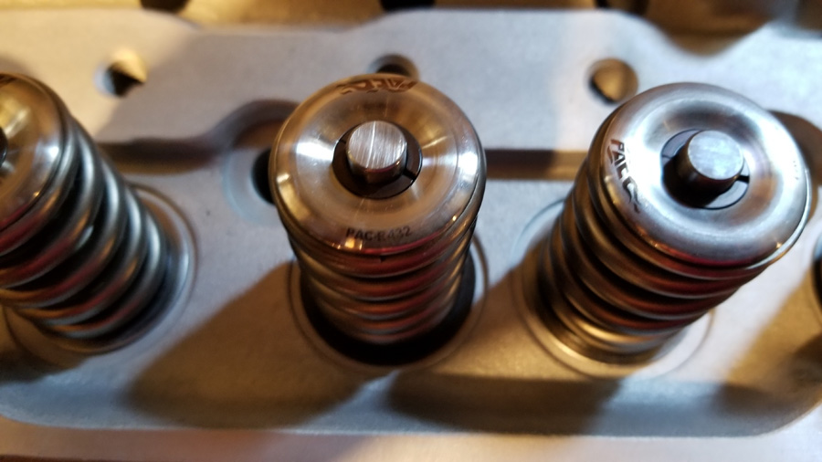
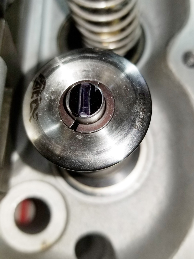
This rebuild used custom Victory titanium valves (flat faced, hard tip), 1.3" PSI springs (lower spring pressure, about 200lbs seat), and PAC locks/titanium TI-64 mini retainers.
The most valve that will fit in these heads are 2.10" intake and 1.625" exhaust.
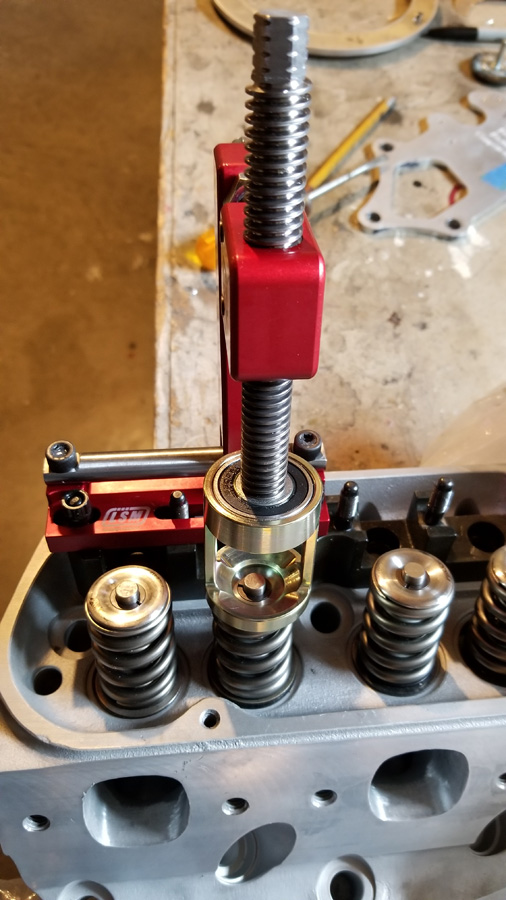
I picked up an LSM SC-150 on head valve compressor tool and this is by far one of the best, if not, the best one that I have used. Works perfectly with the T&D Shaft Rocker Stands and super smooth threading.
T&D provides a handy gage tool that helps set up the geometry depending upon the gross valve lift. This tool is the 0.750" lift tool and the slight gap on the rocker bar was checked to make sure it is correct for the 0.7752" lift. Exact gap should be = (.7752-.750)/2=0.0126" which is half of the difference between gross valve lift and the tool 0.750. This ended up shimming the rocker stands by .030", which resulted in a 0.010" gap, so almost perfect.
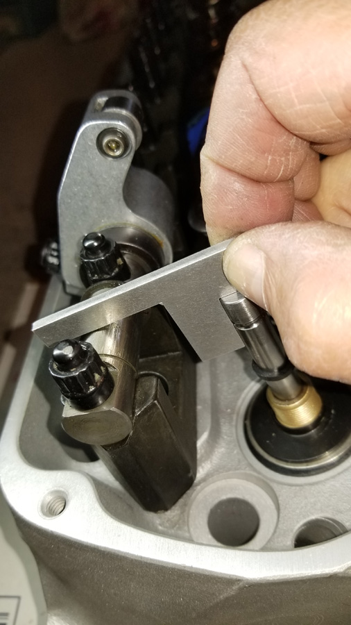
I still always check the sweep as a double check during mock up and I will check this again once the engine is assembled with the cam.
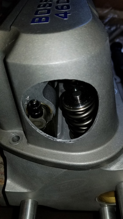
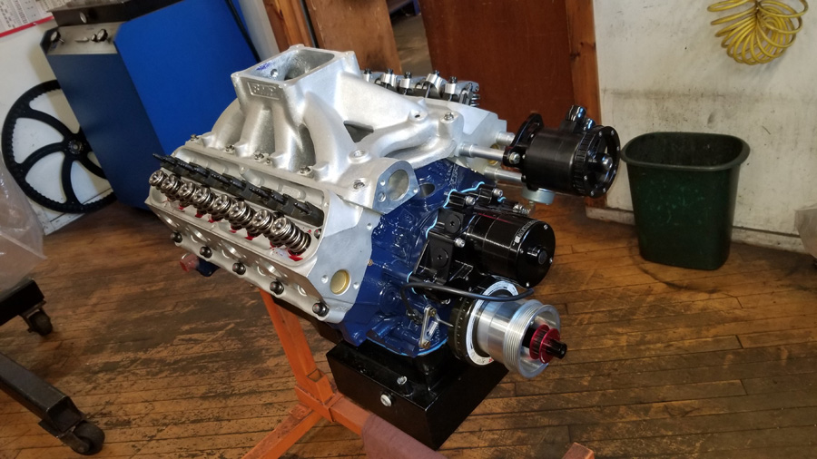
September 27, 2020 - Valve Cover Modifications for Vacuum pump
The new build is using low tension rings and a Star Machine Sportsman Gen 2 Vacuum pump. Star recommends that their baffle be mounted on a vertical surface preferably the front of the valve cover to minimize oil suction. Of course my Ford Racing Cast Aluminum valve covers do not have flat surface in the general area so I had to get creative.
The Star baffle portion that goes inside is just about 2" diagonally, and Star recommends starting with the baffle opening facing down and then rotate it to best reduce oil being sucked in. The first step was to determine if I had an area that I could attached a large enough flat adapter along with clearance between the baffle and the shaft rockers/springs and then drill a hole. Before I drilled the hole I measured many times to be 100% sure and looked on line to see what was available for Aluminum stock that would work.
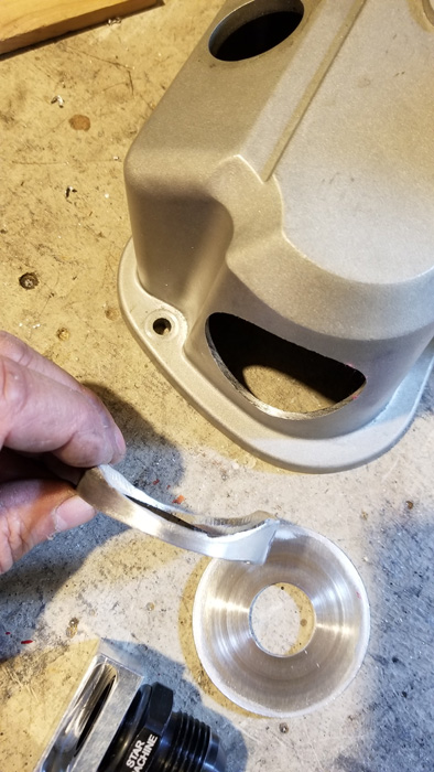
I picked up a piece of 2.5" OD 6061-T6 aluminum pipe with 0.125" wall thickness that is the same thickness as the valve covers and a small sheet of the same thickness.
To template the various curves on the front I wrapped a thin piece of cardboard tightly around the pipe with it slipped over the end by 1". The reason I kept the cardboard on the pipe was to keep it round as I trimmed it. The curve at the bottom of the cover is different than the curve near the top, so I marked up the cardboard and trimmed and trimmed little bits at a time to get as close as possible to the contour. Once the cardboard fit well, I slipped it back on the pipe and used a hand grinder to get the contour close, then used a drill rasp for the final fit.
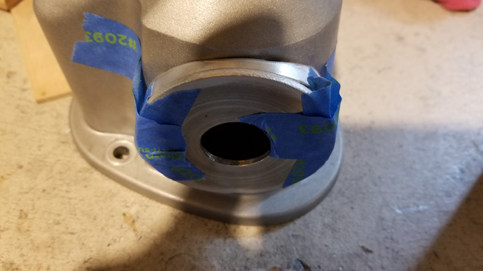
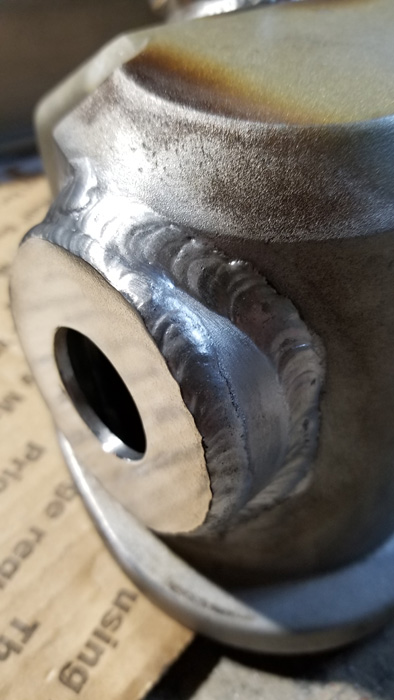
Cut a disc to 2.5" OD and then drilled the Baffle -12AN hole with a step bit. The Star AN fitting uses a rubber O-ring to seal and since I was not sure if there would be any changes from the welding heat the hole was drilled about 1/16" smaller than needed. After welding a rotary grinding stone to size it exactly. The reason Star uses this O-ring method of attachment is to allow you to rotate the baffle as mentioned above and then once an optimal position is determined, it could be welded.
Here is the fish mouth shaped adapter and the end cap.
Disclaimer, I can not take credit for welding the aluminum. A friends son who is an excellent welder did this work for me. The cast AL was a bit challenging. He had to preheat the area with a torch. Also clamped the cover to a thick block of aluminum all around the lip to minimize any warping on the sealing surface since the weld lower weld was about .85" from the bottom.
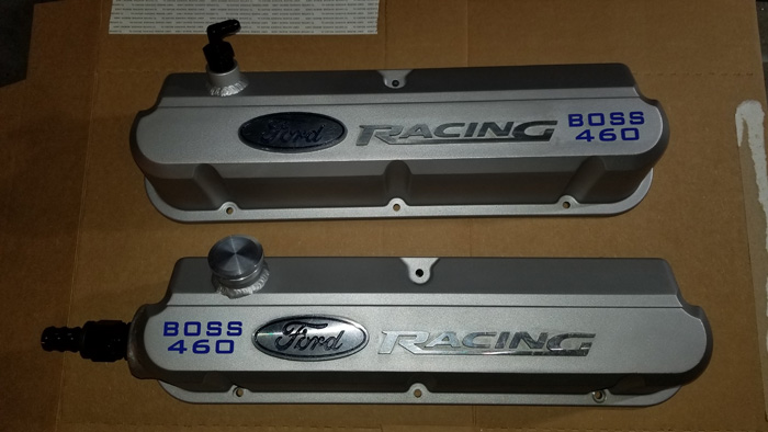
The valve covers were blasted with walnut shells to remove the original finish, followed by the parts washer and refinished with VHT High Temp self etching primer and Aluminum paint. The polished Ford oval and Racing script are cast in, so they were masked off using fineline tape for both the blasting and painting. Here are the completed valve covers. Also welded an O-ring sealing bung for the oil fill, and another bung on the other cover for the vacuum line that will go to the Racepak PANVAC sensor mounted on the firewall.
Finished Product
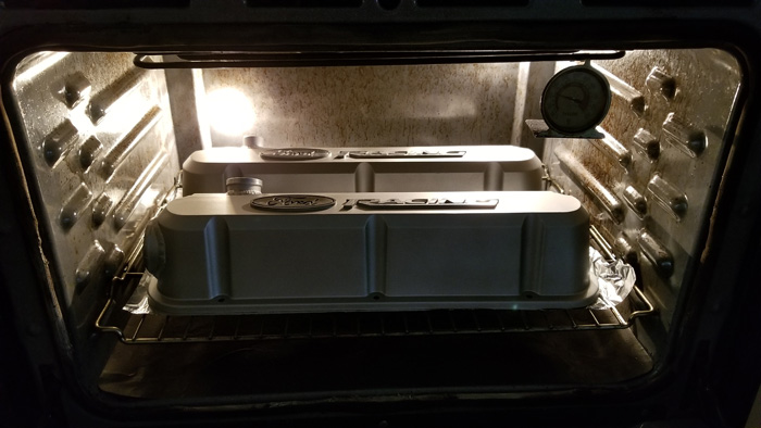
Oh yes, can not forget the baking! VHT Recommends 1 hour at 200* to set the paint. The oven went into Self cleaning mode when I was done :)
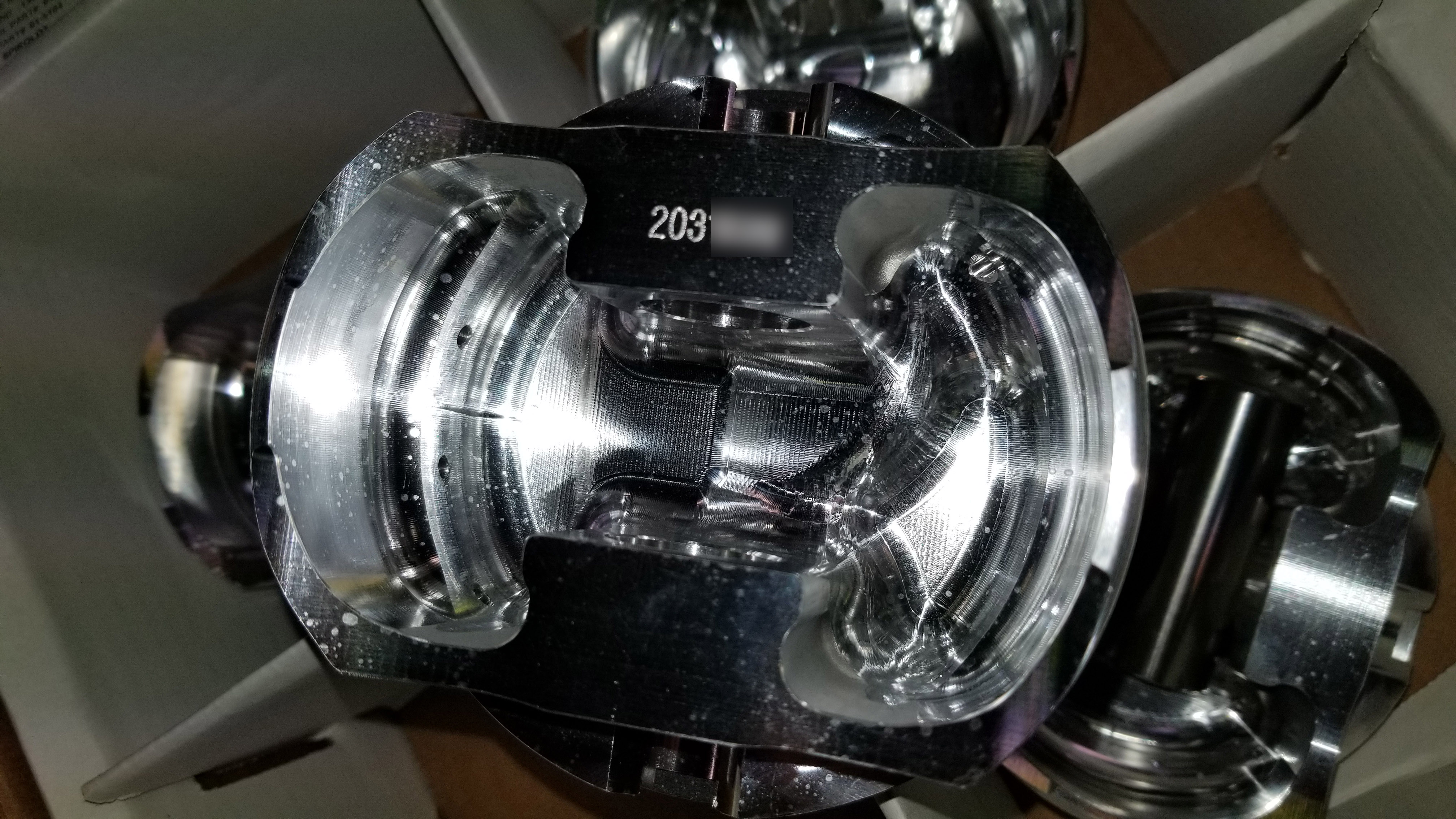
January 15, 2021- Pistons and other parts
The Covid crap has delayed getting some parts, but finally progress is being made. Received the custom Diamond lightweight piston and they look like a piece of art.
Given the small 55cc chamber size and the target of 13.5:1 compression, the pistons have a slight dish.
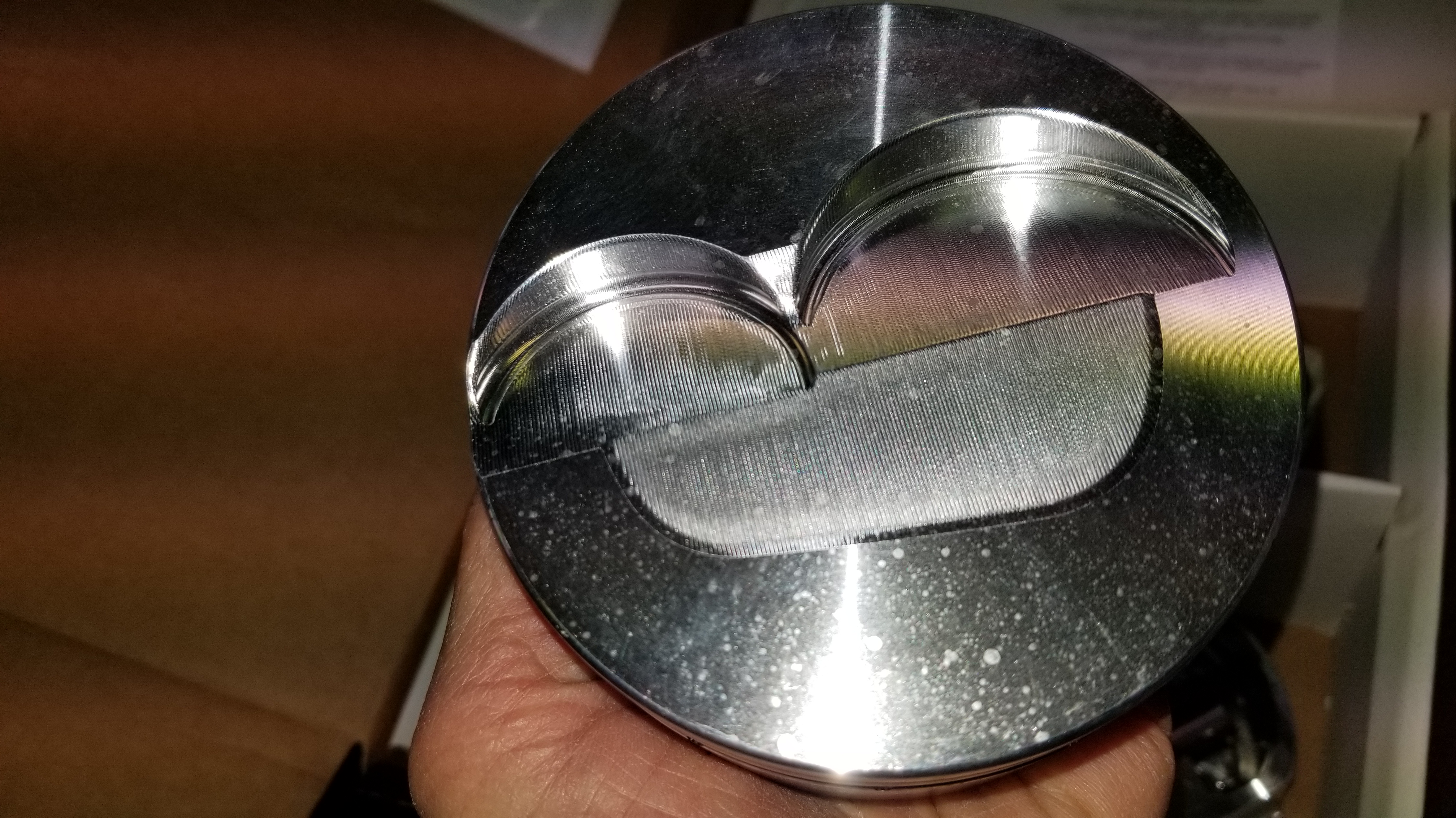
Since I am running a vacuum pump went with the Diamond Pro-Select 1mm/1mm/3mm ring pack. The pistons have the optional for gas ports for the top ring. Went with horizontal ports versus vertical with the expectation that the engine will see some limited street use and do not expect to tear the engine down often.
The undercrown was milled to remove as much material as the application could safely have to further reduce the weight
And the lifters arrived as well. Went with the Isky Extreme Zone EX-Rollmax roller lifters. These are the ones that bushing versus needle bearings.
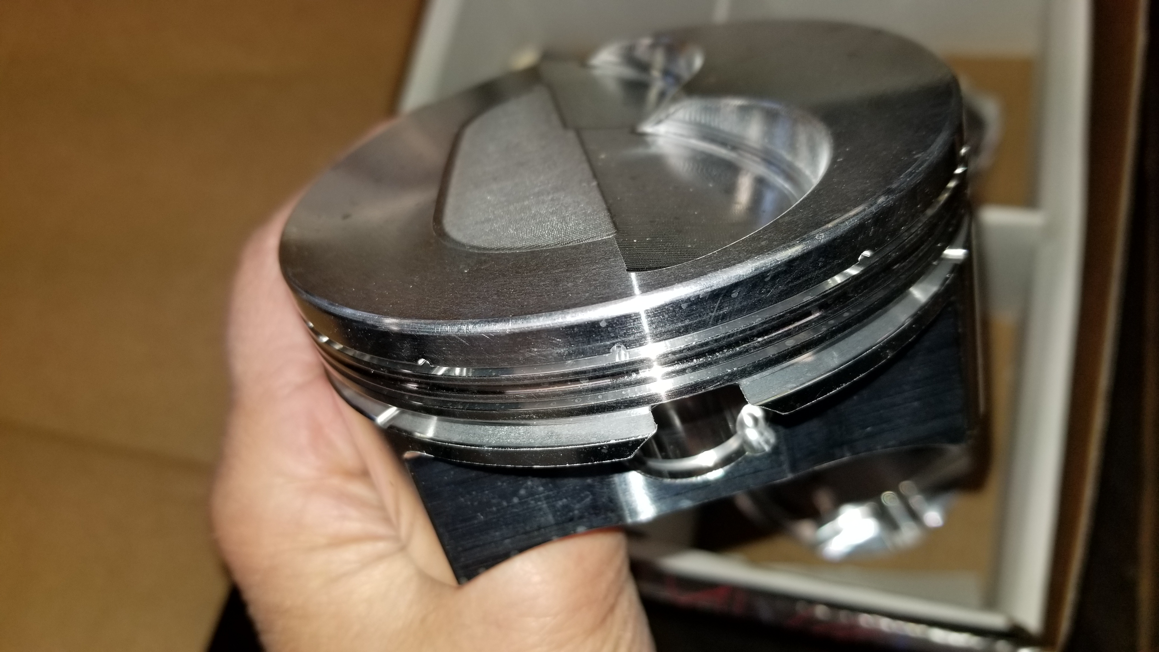
The Molnar Rods arrived, so we have most of the pieces needed for assembly once the block prep has been finished. Went with their 4340 billet Power Adder H-Beam rods that are a bit stronger than their standard rod with a slight increase in weight for a total l= 700 grams (204 reciprocating, 496 rotating) vs. 648gr. They reduce weight by making the rod smaller than the wrist pin end, plus mill some material around the rod bolts (ARP 2000) that providing additional clearance.
January 22,2021- Assembly
The Covid crap has continued to delay things, but now we are on a roll. The first set of pistons had an error so Diamond made a new set. That set us back a bit more. The pictures above have been updated with the new pistons.
This past week Paul at PK Machine did the initial mock up and a few things came up. First was with the big cam, the connecting rods were too close to the cam lobe so they had to be clearanced about .010" near the rod bolt to provide sufficient clearance. Now that we could safely rotate the assembly the intake valve was perfectly centered in the pocket, however, the radial clearance was not sufficient and needed to use a fly-cutter and open up the pocket .010".

Excess stud length on the ARP head studs was trimmed to provide clearance for the T&D rocker stands and the header flanges. After this, the other parts should go together with minimal modifications.
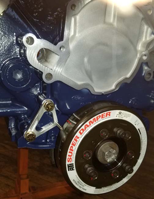
My original pointer would not work with the ATI Super Damper given the larger diameter so Paul fabbed this great looking timing pointer.
Hoping to be on the dyno next week if the rest all goes well!
January 25,2021- Assembly Continued
Things are moving along nicely. Meziere water pump is in place along with the Star Vacuum pump and intake. Intake top surface was milled from 0.0" rear to 0.3" front so the Dominator and airpan will better follow the hood slope. If all of my measurements work out when I bench mocked up the previous setup (Vic Super + 1" Spacer and 4150 carb) versus the new setup (Bill Mitchell Intake, and 4500 Dominator carb) and air pan modification, I had 0.5" to spare and should still fit under the hood without any other modifications to the hood scoop. Fingers crossed.
Initial testing shows good oil flow and about 90psi.
Should have the rest of the pushrods today and the vacuum pump belt tomorrow, so getting closer to firing it up!
January 25,2021- Dyno Testing
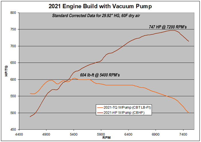
Everything has finally come together and the engine made it on the dyno. There were no issues and everything was right on target (see my comments 5 months ago in this thread stating 740hp). Goal was 740-750 HP and we hit 747HP.
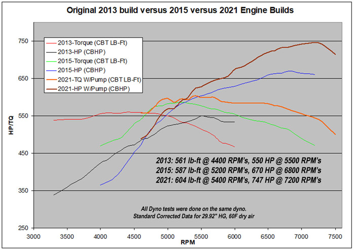
The torque curve was nice and flat and even with this big cam, the idle was still good. Below are some of the results, as well as a showing the vacuum pump gains, and a comparison to the previous builds of this engine over the last 8 years.
The AED custom build 1050 Dominator was nearly perfect out of the box with only the IFR's needing to be slightly changed. We tried a number of changes and ended up being back at the original values. The optimal timing ended up being 25*.
At the end of the day we ended up with 747HP at 7200rpms, and 604 lb-ft at 5400rpms. One thing that is limiting the performance at the top are the headers. With the 70 Mustang shock towers, there is not much room and the 1.75" pipes barely fit, including around the mechanical clutch linkage and steering box. Barely 1/8" clearance around the pipes in some areas. Ideally a 2" pipe would help the big cubes breath at the upper end. Guess I now need to cut out the shock towers :)
The same day that the engine was on the dyno I had it sitting in the engine bay that night, and less than 2 days later it was running. The only issue I ran into was that the vacuum pump does not clear the electric fan shroud (off by .75"), so I need to fab up a relocation bracket to lower it on the left side. Also need a water pump fitting so I can complete the heater core connections- need a defroster on the cool fall nights at the track. As expected the airpan will also need to be modified and my latest mockup shows it will all fit under the hood with the current scoop.
2021 January Build Dyno Video
747 HP
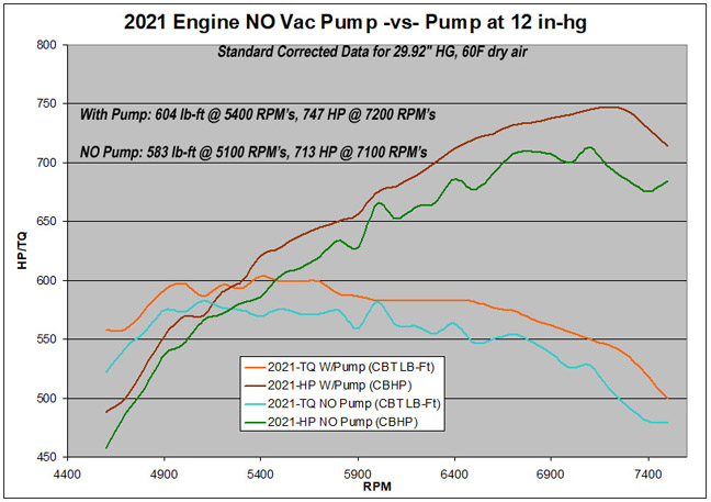
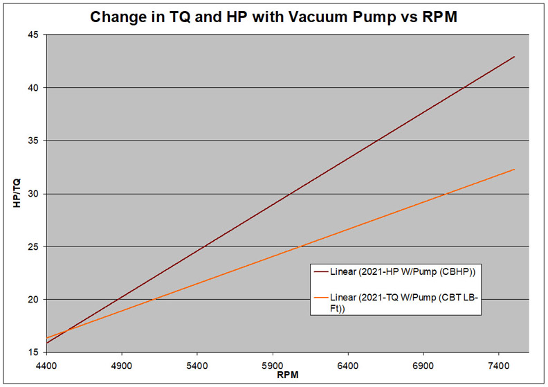
We did two back to back runs, one with the vacuum pump disconnected and the engine vented to atmosphere as compared to the vacuum pump at at 12" hg. You could argue that if there were large breathers versus the valve covers being vented through the AN pump fittings, the difference would not be as drastic.
There may also be some HP left on the table if we increased the vacuum above 12" hg.
This is a comparison of how the engine evolved over the past 7 years as the car transition from more of a street car, to now 90% drag race. Each build extended the RPM operating range, increased torque and HP.
Build 2 (2015) increased the HP by 120, and this latest build by another 77HP.
On the topic of vacuum pump impact on performance, this plot below shows a trend line of TQ and HP versus RPM. You can see as RPM increases the pump has more of an effect. Note that since this is a trend, it is not an exact value of each data point difference, but gives a generalization of how things are changing with rpm.
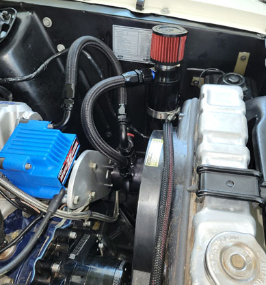
March 15,2021- Vacuum Pump
Wrapping up a few more details and the next thing on the list was to find a place to mount the Star Sportsman Vacuum pump in the engine bay. Using the off the shelf vacuum pump brackets would not work due to pump interference with the electric fan shroud and motor, so I needed to fabricate a relocation bracket to drop the pump. Not many places to fit it, but fortunately there was an area between the lower radiator hose and the left side of the fan motor.
Started off making a rough cardboard template then transferred that to a rigid template using a piece of 1/4" sintra (similar to plexiglas) that I could actually bolt the pump to. This material can be easily cut with a utility knife, but still rigid enough to support the weight of the pump without bending much.
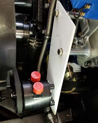
Once the pump was positioned and all of the holes were located the template was transferred to a piece of 3/8 thick 6061 Aluminum.
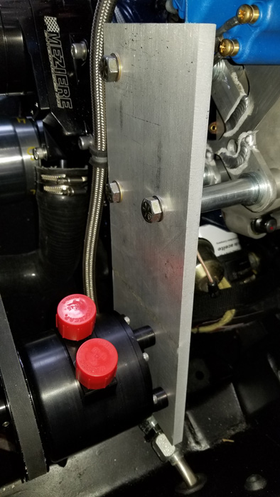
This allowed me to determine the center of the belt adjustment slot and them add some shape to the overall bracket so it did not look just like a block of metal :).
The angle of this picture is deceiving, but the vac pump belt is not close to the electric fan wiring harness.
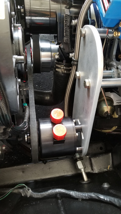
The vacuum regulator is not easily seen in the picture, but is mounted on the pump inlet, and the oil separator is located for easy access to the petcock to drain any oil.