|
Build Blog This page last updated 2-24-2017 **** May take some time to load due to many pictures- Please wait***** |
Page 8
Phase 2- Transformation of the car to more of a Drag car
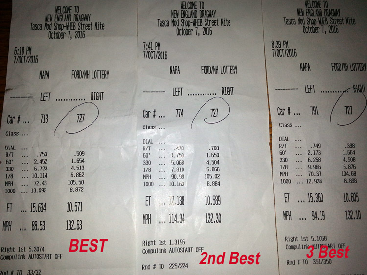
October 7, 2016- New Best Times and highest MPH
Did the initial test of the new G101a a week ago and between poor track prep, damp air, cold temps all day(53F) and me learning the new transmission, my times and speeds were both significantly slower (11.0 sec at 125mph) since I could not hook and broke lose in all gear shifts. Well, this week made up for that with with my absolutely best times ever, and fastest speeds, along with consistency. Part of this was due to a better track, but also included a change in shock settings, and a lower launch RPM off of the 2-step.
Best was 10.571sec @ 132.63MPH. Here are my 3 best time slips. Ignore the reaction times, since I was focusing more on everything else.
Track conditions were definitely better, where all day it was in the 70 deg range, so when racing started at 6pm the track surface was warm and late in the night eventually made it to 50. The track was packed and I was not sure how many passes I would get so my plan was that if I had good times, I would try and make sure things were consistent with minimal changes.
Details on the setup:
1. Clutch: 3 3/4 turns (587lbs), and this was 1/4 turn less than last time.
2. For these runs: Shocks Rebound/Compression: Front 7/14 clicks, Rear 6/13
clicks.
- I did increase the rear compression to 14 and had tire hop, so went back to
13.
3. Launch off the 2-step was 5500 rpms.
- I did increase to 5700, and blew the tires off. Note that with the TKO before,
I was launching at 5800.
4. To minimize changes, as an experiment for shifting, I blipped the accelerator slightly on all gear changes. Note that I was shifting completely without using the clutch and once I get a better handle, should be able to shift even with no accelerator blip.
5. Lastly with my peak HP at 6800 and now trapping at 6300, rear gear change is in order, 4:30's possibly. On my winter list of to do's.
So overall I was happy with the time, but especially with the MPH, since that was a good 3MPH faster than ever. Indicating to me that if I can improve upon hooking up and shifting, I should be in the low 10's.
Here is a video of 2 launches.
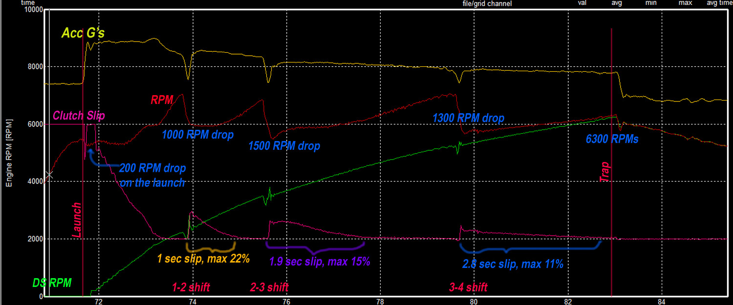
Below is the Racepak data log. The things that stick out to me are:
1. Overall I think the DS RPM's and Acc G's look pretty good. I would like
those interruptions in the DS minimized though.
2. What is considered an acceptable amount of clutch slip and for how long?
The one that I am really questioning is the 4 gear clutch slip that is almost
all of 4th gear. I could not hear it during the run, but it is now obvious from
the logger.
I may need to look at adding to the base pressure of the adjustable clutch?
3. As far as blipping the throttle and RPM drop, I tried to minimize that, so I am surprised to see such a big drop.
Still need to do some tweaking, but it is all fun!
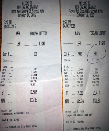
October 14, 2016- Another new best ET and MPH
I made it to the track Friday for probably the last time this season and things are getting better. A new best ET and MPH knocking off about another .1 and adding .7mph for 10.477s @ 133.3mph. 60 foots were minimal change and really do need to improve, so these improvements are mostly from me getting better with the shifting.
I also paid a bit more attention to my reaction times. With the current setup the car responds slower than with the old TKO, so rather than wait for the 4th amber, I am leaving between the 3 and 4th amber.
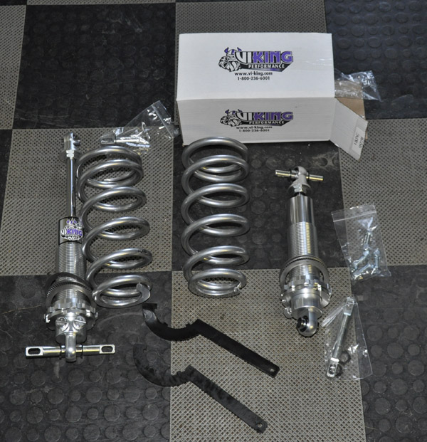
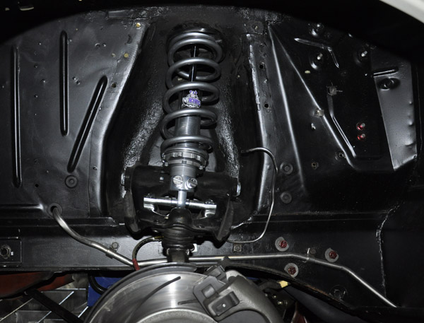
December 28, 2016 - Viking Coil Over Install
Well its winter time here and time to work on the winter projects. Just installed coil overs on the stang. A key reason for this was to allow me to more easily adjust ride height, plus loosen the front a bit more for better weight transfer on the launches.
I was running Viking Shocks on all 4 corners, and swapped out the front ones for Viking Coil overs. I went with the Viking model: A333AP-350SK. I had an extensive discussion with Viking on the application and the spring length and rate, and ended up with a 10" spring with a 350lbs rate.
A nice complete kit. The T-bars on the top and bottom are articulating bearings, so they not only rotate, but flex like a heim joint allowing lots of movement and no binding. The spring adjustment nuts at the base of the shock move nice and easy, and between the spring and the adjustment nuts, there is a roller bearing assembly sandwiched between 2 washers allowing easy rotation.
Install without the shock cover installed, or ride height set. The top of the spring sits right in the shock tower pocket with a prothane insulator at the top.
Ride height now set. It was nice to find out that both left and right sides were at the same height within 1/8" with 22.5 revolutions of the adjustment nut. Also at ride height, I would estimate that there is about 40% spring compression.
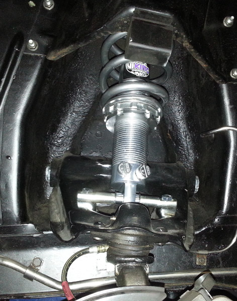
Everything went perfectly and it was nice to handle springs that were not under compression and not worry about them exploding!
After the ride height was set I have just over 5" of front end travel from
ride height to tires just off the ground, so more than the 3.5" before.
Also with the shocks on the loosest settings I can easily move the front end
up and down with one hand so WAY looser than it was before. Absolutely no binding
and I could get the ride height to right where I wanted it.
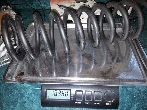
An added benefit is weight savings. The difference between the standard Viking
shock, and the Viking coil over without the spring is .5lbs more, however, the
overall weight from the OEM setup is significantly less.
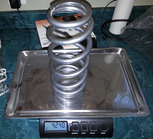
Stock spring = 10.36 lbs, Viking Spring = 4.24lbs, 6.12lbs weight savings
Difference between shock bodies= +.5lbs
Removal of roller spring perches = 2.5lbs each
Total per wheel weight savings is 8.12 lbs, or a total of 16.24lbs.
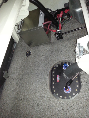
January 31, 2017- Battery Trunk Relocation
The idea of relocating the battery to the trunk became more involved due to me wanting to rewire a number of things and incorporate all of that into the battery relocation and kill switch. Just easier to do it all at once. Some of this rewiring was partly due to the addition of gauges and other stuff since the build started a number years ago. The goal was to make everything nice and neat and easy to trace for adding things and debugging if needed.
So for the battery relocation, I needed to meet NHRA rules for a kill switch
that kills all power from the battery and stops the engine. I took it to the
point making sure absolutely all battery power does not leave the trunk when
the disconnect switch is pushed, along with stopping the engine:
1. A Moroso Super Duty Battery Disconnect Switch, 74102, a dual switch was used
to kill the power to the trunk starter solenoid and a continuous relay for any
other power- see below
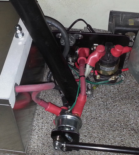
2. A Ford relay is used for the big starter cable (1/0 welding cable) and that
cable is only HOT when cranking. After looking at a number of paths to run this
cable, under the car was not possible with out lots of drilling and wandering
around due to the frame reinforcements and outriggers. The cable runs from the
trunk, inside over the right wheel well where it enters the interior behind
the door, then along the bottom of the door sill, finally exiting through the
floor kick area and right to the starter. This wire is encased in nylon braid,
and any areas where there is the possibility of rubbing, grommets AND fiberglass
sheathing is used, such as where it passes through the floor and where the cable
enters the interior. The small section (about 14") from the floor to the
starter is encased in DEI ultra sheath high temp tubing to protect it from the
headers, and a small bracket holds it close to the block.
3. A continuous relay (Painless Performance High Amp Shut Down Relay 50105) is used to switch all main power from the trunk as well as the alternator charge line. It is turned on/off with the kill switch. Only issue with this is that if left on for an extended period of time it will drain the battery. In my new dash panel I have an indicator LED to remind me to push the switch when I park it- More on that when I write up the new switch panel, and gauge setup.
4. In the trunk there is a ground stud welded to the frame and roll bar plate as a common point for the battery and an additional dedicated ground cable that goes to a stud in the engine bay.
5. Like the starter cable, all wires from the trunk including: Main Power 8GA,
dedicated MSD Box Power 8GA, a dedicated ground (8GA from the battery to the
engine bay GND stud), starter (S-term) control wire, and Fuel pump power (from
interior Relay Panel) are all encased in flexible nylon braid and ran inside
the door sill tray.
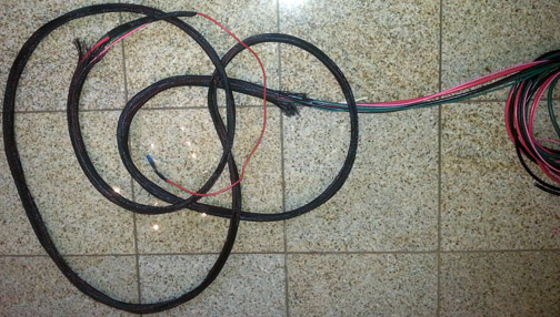
6. For the MSD box power I ran a separate 8GA wire (GREEN), to a lug in the
engine bay, and a second 8AWG (RED) to another stud for the main power.

7. There is a Maxi fuse for the MSD and Main PWR harness in the trunk, and being
overly cautious, I also have another maxi fuse in the engine bay on the alternator
charge wire, so that link is protected at both power sources (BAT and ALT).
8. In addition to breaking the ALT charge line and to minimize toasting the alternator, the kill switch also kills the ignition box through a relay on the relay panel. The tech inspectors always test this to make sure the engine stops, so it will get used.
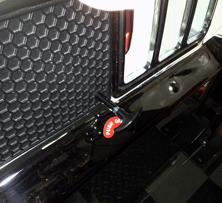
9. I looked at a number is places to locate the Push off handle and decided to exit the rear panel so it is easy seen if it is ever needed.. It goes right through the rear honeycomb panel and fits right in one of the indents, so it can be easily put back to stock with epoxy.
Side notes:
1. My Autolite reproduction battery was too tall to fit in the battery box,
so an Optima Redtop is used. Can't see it so do not care.
2. Some massaging of the rear wheel well was required since the battery box
barely fit because of the roll bar. I had to get creative with how I put the
battery in the box.
3. For 8GA and thicker cables, I used a 10 Ton hydraulic crimper which did a
great job and every terminal used heat shrink tubing with adhesive inside for
added reliability.
February 3, 2017 - Relay and Electrical Panel
Continuing with the electrical work I decided to organize all of my relays and other electrical stuff on a panel. The core of this panel is a Nitrous Dave 10 Circuit Relay Center with 5 fused 40 amp circuits and 5 fused 20 amp circuits. The relays are socketed and fused, as well as small LEDs on the relay trigger as well as output sides to aid in testing and knowing when a circuit is active. The panel just made it easier than using a bunch of separate relays. Right now I am not using all circuits, but expect to, as I add things such as an electric fans and water pump in the future. There are 3 stand alone relays in the upper right that are used due to needed flexibility that the panel did not allow. One is for killing the ignition box that works in conjunction with the trunk kill switch, and the other two are part of the latching circuit for the 2-step and line lock released by the clutch pedal switch.
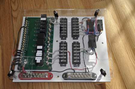
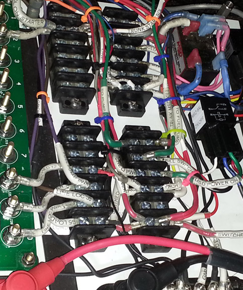
All wires are high quality TXL or GLX Automotive wire and every terminal is
crimped and soldered, with adhesive lined heat shrink tubing for added reliability.
I picked up a Dymo Rhimo 4200 label printer that would print on heat shrink
tubing so every wire is labeled on both ends, as well as some along the way
for easy identification. Labels and wire colors match the schematics I put together
so in a year when old age kicks in and I completely forgot what I did, I can
figure it out Its hard to see under the wires, but all of the terminal strips
have labels on the board as well.
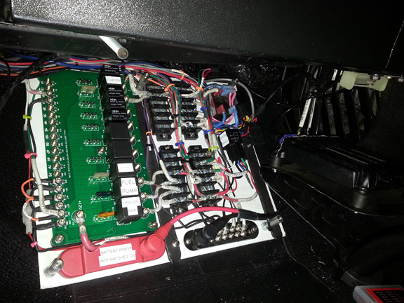
Mounted the panel on the passengers side kick area with 4 nutcerts in the floor
for easy removal and there is enough slack in the harness that I can move the
entire board out onto the floor for additional access if needed.
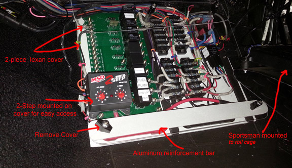
There were two concerns that I needed to address with the location. First was a passenger kicking the panel, and second was a heater core leak dripping water on the panel (yes these old stangs are known for that). To address both I fabbed a 2 piece Lexan panel that covers it and wraps right to the floor panel. It will do a decent job for protection. It can quickly be removed with 4 twist knobs.
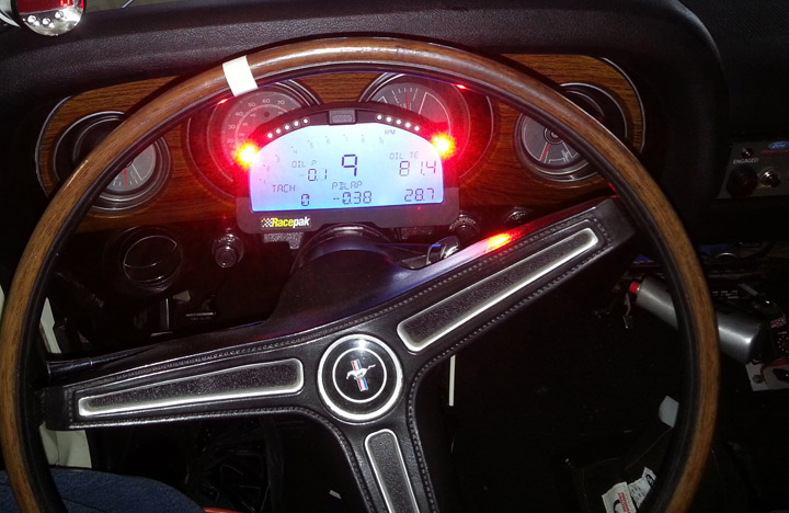
February 7, 2017 - Switch Panel and Racepak IQ3 dash
Finally wrapped up the wiring.
If you see at the beginning of this thread (yes the very beginning when I first started the build a few years ago) I had a number of gauges inside of my console box and in the front area of the console with a dual gauge pod. The console box also had some switches to enable to line loc, 2-step, and start the data logger. With the install of the GForce race transmission last fall and the modifications of the transmission tunnel, the console no longer fit so I needed somewhere to put all of this.
I decided to use a RacePak IQ3 display dash that works with my Sportsman data logger. This way I can have all gauges (up to 20) in one display with multiple pages. Some of the things that are monitored (and or logged) include: RPM, Volts, A/F, Drive shaft speed, clutch slip, Water Temp, Oil Temp, Oil Pressure, Vacuum, Fuel Pressure, Acc G's, Lateral G's.
The display is attached to the steering column so I would not mess up the original dash/gauges which still function and the harness is enclosed behind the display.
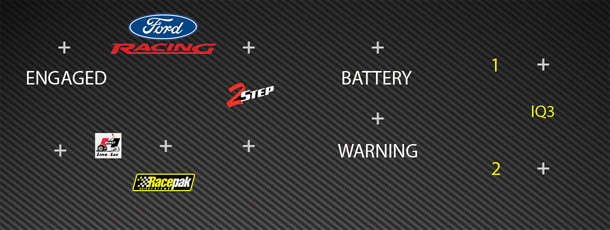
For all of the switches and indicator LED'S I created a custom panel that fit
right into the Air Conditioner Vent frame. I had removed the AC a year ago,
so the vent was not being used and only for looks.
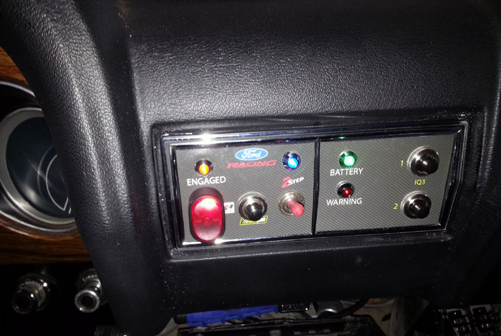
Left Panel:
Switches left to right in order that they would be activated as I stage: Enable
Line Loc, Start Data logging, Enable 2-Step. I also selected different switch
types so I could feel the difference.
Leds: Amber/Engaged = Line Loc actually engaged when the shifter button is pressed,
Blue=2-Step Active. Note that when staged, the LineLoc and 2-step are released
off of the clutch pedal switch.
Right Panel:
Leds: Green= Battery Kill switch active, RED= Programmable Warning from IQ3,
Switches: IQ3 button 1 and 2
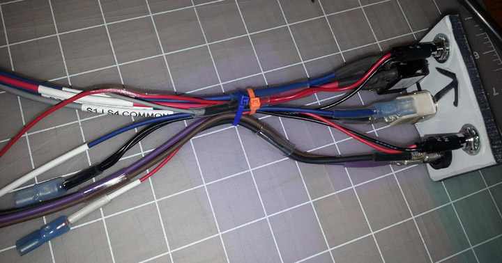
I removed the adjustable air direction vents and created 2 panels that would
snap in. The panels are made out of sintra, which is durable, yet easy to drill
and form.
To create the panel image, generated some artwork to exact scale so I could
locate the switches and LEDs and create a visual mockup.
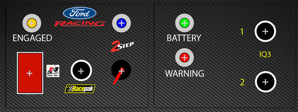
Then created an image that I could print out on photo vinyl, laminate it on
the panels, drill where the + signs are and just assemble it. This included
all of the logos and lettering. I also decided to give a slight carbon fiber
effect in the background.
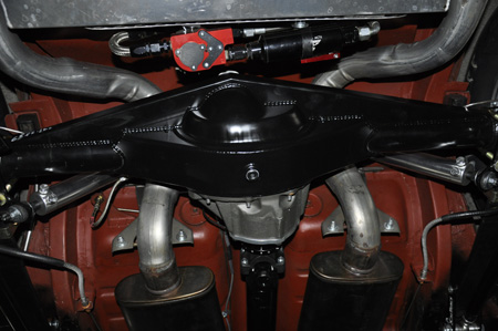
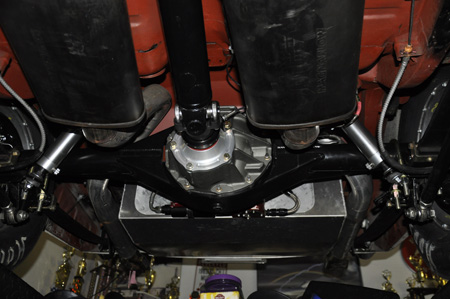
February 11, 2017 - New Rear End Installed
With the increase in HP/TQ last year, and the install of the GForce G101a, I was really pushing the OEM rear end housing (31 spline axles/TruTrac) and it was the weak link in the driveline. Part of this winters list of projects was to install something much stronger.
Purchased a Heavy Duty Strange Crate Rear End
Had them reinforce it with Boxed-in Spring Perches and add a back brace
Powder coated
Center section is 9" PRO IRON with a Light Weight 4.30:1 Spool
35 SPLINE Pro Race Custom axles with 5 lightening holes
According to strange, should be good for 1000HP+
The 4:30's should have me trapping at about 6800-7000rpms, right near the peak and with the 3.17 first gear, should be very quick off the line.
Took it for a quick ride before the snow and it feels great!
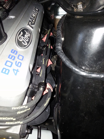
February 14, 2017 - New Plug wires-FireCore50
It was time for some new plug wires, so after reading some very good reviews on the YellowBullet forum, I decided to give the FireCore50 wires a shot. One thing that I really liked when I first looked at these were the long boots that they call Promod 45 Boots. With my current wires, it is a total PIA to get the wires on and off near the shock towers, and even the end ones due to the headers and the thick header flange. In the past to get the plug wires off I need to use plug wire pliers or another small tool I have, and it is still a pain.
With these extra long boots and the integral area to grab, no tools needed and I can get them more easily on and off. They are more expensive than the general ones out there, but the quality is excellent, and super fast turnaround time- less than a week to my door. I sent them my wire lengths to be custom made so they would be routed as I wanted.
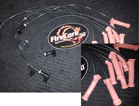
They come with wire markers installed as well. The boots on both ends grab very
well and a good positive click indication of them being locked on.
You can see how tight it is, and how these stick out giving something to grab
onto.
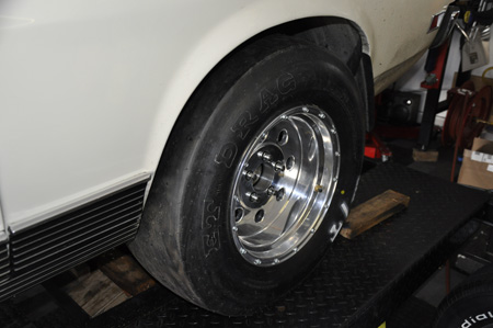
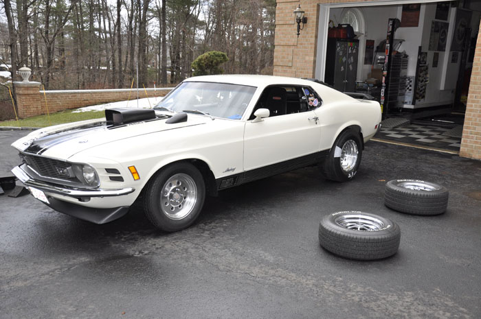
February 22, 2017 - New Wheels & Tires
With the track opening in a month I stepped up my tire from last year and went with an all out slick as well as a wider wheel so the tire does not crown. For tires, went with MT 3055S tires, which are 28"x10.5x 15", that has a 12.3" section width. These are stiff sidewall tires and for added stiffness, running tubes. Last year I was killing the sidewall on my Hoosier QTP's and that was impacting my 60's. Plus, this will give a bit more stability at the big end. These are mounted on 10" wide wheels with a 5.5" backspacing.
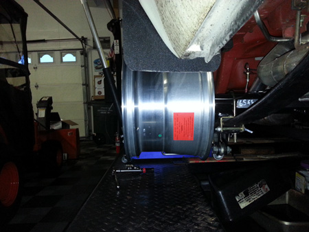
There is a good 1.25" of clearance between the tire and leaf spring, and
in front of the tire about 1.2". Called MT tech and they said that is enough
clearance, since the combo with tubes will grow about 1"to 1.5" in
diameter between 130-150MPH, and I will be around 135MPH. In any case, I am
going to roll/clearance the front bottom lip edge of the wheel opening just
a little to get some added clearance for tire growth and my comfort.
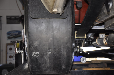
The tire only sticks out a little at the center section area.
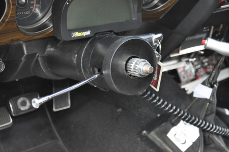
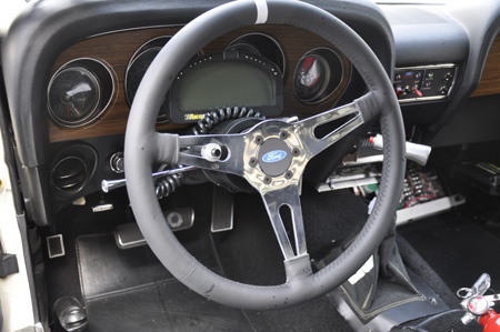
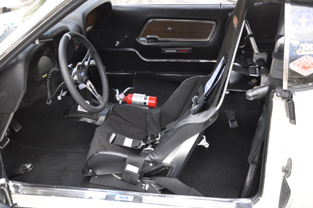
February 24, 2017 - Removable steering wheel & Kirkey Race seat
I am finally at the end of my winter project list, of course there will be other small stuff I am sure. Part of the work this winter was not only to go faster, but also for safety. This included the trunk battery/kill switch, lots of rewiring and now a Kirkey seat and a removable steering wheel. Also had to get Stroud to recertify my belts since they were 2 years old. They look like new again.
For a removable steering wheel, I wanted the ability to put my stock steering wheel back on in the future. Most of the quick release hubs require welding to the column. Cobra automotive has one that bolts on. A bit pricy, but very well made and easy to align and get the wheel on/off. The large spline with the disconnect rib, fits over the stock spline for a secure fit just like the OEM wheel. In fact to get it off, I needed to use a pulley puller after it was unbolted.
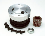
Only thing is that it does not cover the column opening so I had to make a cap
that I can pop on/off.
Went with a Moto-Lita wheel and added a horn button into one of the spokes on
a spiral coard for those times I will drive on the street. The wheel has a rubber
core and leather wrapped, nice and thick, but not heavy so it fills my hands
for a good grip. Made a center Ford button for the wheel with a carbon fiber
look that matches my switch panel.
Installed a Kirkey seat (41 Series Aluminum Pro Street Drag) to provide better
support than the OEM bucket seat I had. I never felt completely secure in the
OEM seat even with the 5-point harness. If the Kirkey floor mounts were 1"
bigger on the bottom they would of worked perfectly with the floor holes. I
ended up making my own floor mounts using the Kirkey ones as a template and
had a local metal shop make the bend. When I installed the roll bar a few years
back, the floor pan area was also reinforced, so the seat base is well secured.
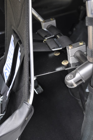
Then fabbed up a back support that allowed some adjustment and used heavy duty saddle clamps to mount to the bar..
I fabbed it out of aluminum and used 2 heady duty saddle clamps to mount it to the roll bar. The clamps were made by DX Engineering.
The horizontal portion has an a bend that attaches to the seat (approx 110 degrees) and aligns with the layback, as well as is curved to the seat back. It is attached with 4 button head bolts. Then there is another horizontal piece that attaches to the 2 clamps with 4 bolts that go through the clamps. The two horizontal sections overlap and are bolted together allowing for some forward/read adjustment. Everything is GR 8.
I could of just used one piece of aluminum for the horizontal section and get rid of any adjustment, but it is set up for 2 seat positions that I can move within 10 minutes. The 2nd one is for my wife who does drive at times.
There was a number of ways I could of done this and I had drawn up another design that used locking pins for very quick adjustment, but did not feel it was solid enough.
The seat is "rock solid" and no movement in any direction.
-------------------------------------------------------------